Ad Widget

Collapse

Announcement

Collapse
No announcement yet.

JCM 800 2203 dead...

Collapse
X
 
  • Filter
  • Time
  • Show
Clear All
new posts

  • #61
    Originally posted by stokes View Post
    Mitch,you are missing the point here.What we need to do is find out what is blowing the fuse,when a fuse blows it means there is a short somewhere.This test is to determine that there is no short in the filter caps.I need you to take all the tubes out and turn the amp on and see what the volts at each cap is starting at the rectifier and working your way down to the last filter in the preamp.There is no need to measure the 0volts at ground,also it appears that the first two caps are stacked one cap grounded and another in series with it,I dont need the volts in between where you see the 470 is the B+ feed that 230 is where the two caps are connected together,we dont need the 230.With no tubes there is nothing to draw current so the voltages should be the same at each cap,if we see a voltage drop at one of the caps it will indicate that cap is drawing current,and is either leaky or shorted.Look at the schem.you will see the rectifier feeding one cap then the choke then another cap then a resistor then another cap another resistor and finally the last cap in the B+ rail.These are the voltages I need to see.
    I'm confused though if I know what the B+ between ground is, which is 470, and I measure all the other caps to ground which is what I did is that not just the same thing really? the first cap conencts directly to the B+ through the rectifier, so its 470, if I measure between what I had labeled as cap I and cap V I'm just going to get the difference in potential between the tow and I can tell you thats 130v. and when i measure it, its 130v. when I measure it thats what I get. Cap I is C23 n the schematic no? thats where I start, I keep one probe there and then with the other I then each probe in relation to it? what I did last time was measure each cap to ground and like I said I don't see the difference?

    and as for the fuse that was just extra information I understand what we are trying to find out even if I may not understand exactly how to find it out. I just thought it was odd that that fuse was blown because it was blown before aswell, like even when I could get the amp to come on fine and it seems odd that that would be the case.

    Comment


    • #62
      Mitch,when there are no tubes in the amp the only thing to draw any current in the B+ rail would be the caps,if they are not shorted or leaky they wont draw any current,therefore all the voltages will be the same at C23,C22,C21-C21 has two 50uf caps seperated by a 10k resistor so lets call that C21a and C21b.So give me the voltages of these four C23 thru C21a&b from each one to ground.And this must be with the tubes out of the amp.If the readings you gave me before are with the tubes removed,I see a big drop in volts which should not be there.Now using the cap designations from the schem (C23 etc.) to make it clear where this voltage drop is measure each one to ground with no tubes in the amp.

      Comment


      • #63
        ok so in the first post I took a reading from each cap to ground, no tubes in, and amp is fully on, not on standby, in my picture cap I is c23 on the schematic, Cap II is C22 and then the one not pictured would be C21. I don't know what cap V is though I only see 3 of these caps on the schematic.

        Comment


        • #64
          Okay it looks like you are dropping too much voltage from that last post but I am not clear on exactly what you are showing me.What is IIg?That is why I asked to use the schem symbols such as C23 etc. and give me the voltages at just those four points,you are dropping 240vdc across a 10k resistor and that is not good,and I want to be sure so that is why I want you to measure it again and give me C23-470v,C22-xxxv C21a-xxxv C21b-xxxv.There should be no more than a 1 or 2 volt difference with no load in there between those caps,and 240 is way out of line.

          Comment


          • #65
            IIG is the ground terminal on C22

            C23-500v
            C22-500v
            C21a- 315v
            c21b- 305v

            C21 is not two caps totem poled though. C21 is a single 50uf/50uf cap it has the 10k ohm resistor between the terminals and I get a reading of 315v before the resistor (c21a) and 305v after it(c21b).

            (values are a bit higher than before because I was reading puring peak hours and its later now, well I assume thats the difference anyways)

            and also the voltage on what I have labeled as cap V on my picture and which I can't find on the schematic (it connects to C22 through two 10k ohm resistors in series which are also paralleled into the preamp circuit) is 400V

            Comment


            • #66
              Okay,now is C21a connected to what you were calling 11g?Or is it connected to the + side of C22 by way of a 10k resistor.You see the 185 volt drop from C22 to C21a?That should not be there,according to the way it is shown in the schem.I have.I also dont see the cap you describe as V in the schem,I have to wonder now if somebody changed something in that amp.Do you know if the power supply has been modded by anyone?What exactly is cap V feeding?Is there an extra 12AX7 in this amp?Sorry for all the questions but I want to be clear on some things and it looks like there is a problem in that power supply,a ten volt drop would indicate a leaky cap,and you are dropping 185 volts.

              Comment


              • #67
                C21a connects to C21b (the other terminal on the same cap) through the 10k resistor it doesn't directly conenct to the ground pin of C22 which is what had labeled as IIg.

                I jsut want to be totally clear, when we talk about c21a and c21b we are talking about the same dual cap right? just using A and B to signify which side of the one physical cap that is there.

                C21 is the cap in the preamp section, it is where the voltage drop is. both C22 and C23 read same as the B+

                as for "CAP V" I'll have to trace it out when I get home. There is no extra pre-tube but I was planning on adding one at one point if you have an information to share . As I said though "CAP V" does end up back at C22, but also conencts in parallel to the preamp circuit but I'll have to trace out exactly where when I get home.

                So whats the hypothesis? a short between C22 and C21? is there anything else I can start checking aswell?

                Comment


                • #68
                  I know C21a and C21b connect to each other via a 10k that is what I said to begin with.I need to look backwards and see where C21a connects to the power supply.Let me try to simplify this.The B+ voltage flows from the rectifier to C23 thru a choke to C22 thru a 10k resistor to C21a thru a 10k to C21b.That is the schem.Now you tell me the amp has another you call cap V.I have to be sure where C21a connects going back away from C21b.Forget "capV connects in parallel to the preamp",that tells me nothing.It should connect to a preamp tubes plate by way of a plate resistor,something in this power supply has been changed,you dont have enough tubes for that extra cap,V.As for hypthesis,it is too early to tell but yes,it looks like C21 is shorted or extremely leaky but till we get this power supply sorted out I cant be sure.

                  Comment


                  • #69
                    Sooooooooo. It took a while to figure all this out but here it is:

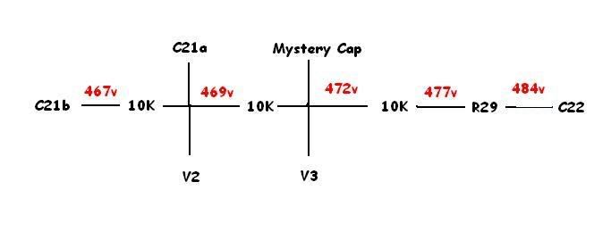
                    the schematic and my amp are not totally the same. I don't think it was modified because all this stuff is right on the pcb and the pcb is marked to match it and the mystery cap has all the same mounting hardware etc, it seems to be the exact same type of cap as all the rest. This amp is a very early version of the 2203 I believe, it has has the older switches on it not the black and red switch that most of them have, I think its a model made for the Canadian market as well? but anyways here are the changes; On the schematic, C22 connects to R29 which splits off to V3 through R21, but more importantly connects to C21a:

                    C22 --> R29 --> C21A

                    BUT in my amp there are a bunch of other 10k resistors. heres what it looks like:


                    So I'm thinking with all the resistors the voltage drop makes sense? although the drop doesn't seem consistent? and any word on what that mystery cap is doing? whats its purpose?

                    where can I go from here?

                    Comment


                    • #70
                      No,a voltage drop does not make sense,with no tubes there is nothing connecting the B+ to ground,the circuit is gone when you pull the tube therefore no current is being drawn,there should be no voltage drop across any resistor between any of the caps.According to your drawing if that is all the mystery cap is tied to it looks like it feeds the PI V3.I assume C21b is feeding both plates of V1.C22 is feeding the screens of your power tubes and C23 is connected to the CT of the OT primary.Assuming all the measurements you are showing me are correct,and the connections I just pointed out are right,I am going to take a guess and say those caps are original.As I have been saying all along with no tubes in the amp,you should not see a voltage drop of more than 2 volts across any of the resistors between the caps.If you have 475 at the rectifier you should have no less than 472 or 473 at the other end and at every cap in between.You need a cap job.You have leaks at every point in that B+ rail indicating those caps are leaking.If they are original you are way overdue.

                      Comment


                      • #71
                        Not a real mystery, just a little extra decoupling. All those resistors may be 10k nominally, but we need to measure them out of circuit to be sure. I calculate that each 10k has somewher in the 4ma to 6ma area of current coursing through it. Each is a little different due to variations in the parts themselves and possible parallel paths.

                        The current through the whole thing seems to be fairly consistent actually, and I am led to wonder what there is off the left end that is dragging those few mills off C21b.
                        Education is what you're left with after you have forgotten what you have learned.

                        Comment


                        • #72
                          I have never checked the volts on an amp with good filter caps that showed a voltage drop of over 2-3 volts anywhere down the whole line,even with 20k dropers in the line.Those caps are leaky,unless he has tubes in the amp,there is nothing in the B+ rail to draw current except the caps,and they aint supposed to draw current without the tube to complete the circuit to ground and at that they only draw for a split second till they charge up.With no tube the only thing connected to ground is the cap,wich blocks dc ,unless it is leaky.All those drops are way too much,those caps are leaky.

                          Comment


                          • #73
                            alright, so I messed up again, while I had taken all of the power tubes out, I just didn't even think about the preamp tubes.

                            here it is without the preamp tubes:

                            Comment


                            • #74
                              That is more like it. You have maybe half a mill or less leakage current.
                              Education is what you're left with after you have forgotten what you have learned.

                              Comment


                              • #75
                                Still too much current being drawn with no tubes,in my experience.You say this is an older amp,I'll ask again,are those the original caps?The fact that the fuse doesnt blow immediately when you power up,indicates a leak rather than a dead short.

                                Comment

                                Working...
                                X