Ad Widget

Collapse

Announcement

Collapse
No announcement yet.

Traynor BassMate EL84s full of blackedned getter material?

Collapse
X
 
  • Filter
  • Time
  • Show
Clear All
new posts

  • Traynor BassMate EL84s full of blackedned getter material?

    Hi, I've had a Traynor BassMate for about 15 years. It's always had some issue that I could ignore by merely cycling the power and getting it to settle in. I hardly use the amp. It's real clean but getting old.

    The other day it finally seemed to die and only made a farting type sound.

    I pulled the chassis. All I can find wrong is that the EL84 tubes are blackened with what I assume is getter material. The circuit itself seems stable.

    It's all original caps etc... maybe a fresh bias supply cap was installed a while ago.

    I placed two new Sovtek EL84s I had on the shelf and it just sounds great. better than ever.

    So I went ahead and checked some voltages. They all seem stable but a bit higher than I expected.

    I don't know what else to do preventative maintenance wise. I'm wondering if the tubes just finally wore out (I've never seen them so black) or if there is some other failing componet I should suspect as the real casue of the problems.

    I can do a cap job but the amp is so clean right now... I'm hesitant to do a cap job just for the sake of it.

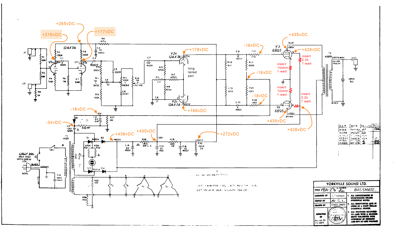
    I'm seeking advice about the voltages. The B+ seems high and the -18vDc at the cathodes is about half of what I'm familiar with 6v6 circuits.

    Here's a link to the schematic that I think applies to my amp, I've notated it with the voltages I'm measuring:

    http://harmoniccycle.com/hc/images/g...ate-YBA-2B.gif

    best regards,
    mike

  • #2
    I'm not an expert (or anywhere close!) But I'd think that yes, your power tubes just gave up on you. This is a combo amp, correct? EL84s and combo amps don't seem to add up to longevity for the tubes (and yet the market is flooded with them these days - tube manufacturer consipiracy, perhaps? ) because of all the vibration from the speaker. I saw someone somewhere refer to EL84 combo amps as "tube torture chambers"...

    As for the voltages - what are you getting out of your wall? The schematic measurements are at 115VAC, I know in my house I get more like 122VAC so that'll have a little influence on your readings. I can't be of much help as to what any problems may be, as I'm still teaching myself these tube circuit basics...

    My only other advice - if it sounds good, and has no bad capacitor hum - then if it ain't broke, don't fix it!

    Comment


    • #3
      Originally posted by f13ndus View Post
      I saw someone somewhere refer to EL84 combo amps as "tube torture chambers"...
      That may have been me in a thread about the Crate VC series. They put those little 84s right on top of the speaker(s) and it doesn't take long to rattle the internal structure halfway to death.
      The farmer takes a wife, the barber takes a pole....

      Comment


      • #4
        Thanks to both for sharing your thoughts. Yes, it's a combo amp.

        I need to make a correction to one thing I said above.

        I said the cathodes were at -18vDC... it's the screens that I measured at -18vDc.

        The cathodes are directly connected to ground.

        best regards,
        mike

        Comment


        • #5
          Originally posted by mike_mccue View Post
          Thanks to both for sharing your thoughts. Yes, it's a combo amp.

          I need to make a correction to one thing I said above.

          I said the cathodes were at -18vDC... it's the screens that I measured at -18vDc.

          The cathodes are directly connected to ground.

          best regards,
          mike
          Are you sure it's not the grids that measure -18V?

          Comment


          • #6
            Hi,
            I guess I was using the term screen and grid interchangeably. I made a simple mistake by mis stating the measurement at the cathode.

            If I'm mistaken about the use of the terms screen and grid then that's a deeper problem... please elaborate if I need to learn something about how to make best use of the terms screen and grid.

            I have updated the schematic with more in depth voltage measurements:


            The -18vDc measurement is actually close to the -16vDC specified on the schematic so I'm no longer as confused about that.

            I have noted some unusual voltages at v1 and v2... so I think I'll check the resistors and RnR some caps to see if that can meet spec.

            A friend and mentor has advised me to add a few resistors in the power stage... indicated in red.


            I welcome any suggestions... thanks!

            best regards,
            mike

            Comment


            • #7
              Hi Mike,

              The control grid (G1, or Grid) is where the signal enters the tube. The screen grid (G2 or Screen Grid) allows more efficient operation (than a simple triode) by helping to keep exited electrons moving towards the plate and not bouncing back to the control grid (it's not as positive as the plate, but way more positive than the grid).

              As for your measurements: it looks like the plate load resistor (100K/R8) on the 2nd stage has drifted high. The slightly high bias V (-18V) is better than too low; as the tubes will run cooler. It seems that your friend has advised the 10 ohm cathode resistors so you can more safely measure the output tube dissipation. I'd advise 1 ohm (1%) resistors for that; then the voltage (mV) you measure across it can be converted directly as amperage (mA). The 2.2K screen resistors he's advised are a bit high, and might throttle the outout back a bit too much; I'd use 1K/5W parts here.

              Concerning the unusual voltages at v1 and v2; measure for DC voltage at the grid of V1b, and the junction of C3 and R10. Don't change these caps; Traynor used good caps here (usually mullard "mustard" caps) and they're not likely the problem; check/replace R8. I don't see any unusual voltages at V2.

              Hope this helps,
              DC

              Comment


              • #8
                Dave,

                Thanks very much for the detailed explanation and suggestions.

                The caps are as you describe. I will check the resistor first.

                The other advice about the extra resistors makes good sense as well.

                very best,
                mike

                Comment


                • #9
                  You're more than welcome, Mike. Keep us posted; we like follow-ups!

                  Good luck!

                  Comment

                  Working...
                  X