 Tweet
Tweet
I did a search on this Fender amp and didn'y find much if anything on setting the output tubes bias. What's the procedure for setting the bias on the earlier (6G12) Concert amp?
-
-
Exactly like you would for any other amp.
What output tubes are you using?
What is your target dissipation?
What is the B+?
How much current at that B+ voltage is required for the target dissipation?
Set bias for that current.
Then recheck for any change in B+ and adjust if necessary.Education is what you're left with after you have forgotten what you have learned. -
I think he's asking what to change when there's no pot to set the bias with.Originally posted by Enzo View Post
The 10k resistor in the bias circuit schematic suggests itself. It's a bit of cut and try. At this point I would probably evaluate the 220k resistors carefully and make sure they're as close to each other as possible. That way, that matched set of tubes will stay matched when they're placed in your amp.Comment
-
2 methods, (always read plate current NOT negative voltage, using bias probes/1ohm cathode resistors/transformer shunt)...
1) Try a bunch of power tubes until you get a matched set running at 30-35mA each. (B+ should be around the 500v mark at a reasonable bias current).
2) As Dawg says, adjust the bias circuit - reducing the value of the 10K dropping resistor will cool the bias. Or, replace the 56K bias load resistor with a 39K fixed resistor to ground and a 50K cermet trim pot wired as a variable resistor. If you use the long rectangular top adjust type you can fit it between the 8uf caps and secure it in place with a dab of silicon cement. Now you have adjustable fixed bias, replace the original 10K with whatever value gives you the ideal range of adjustment, say up to 40mA with your chosen tubes?
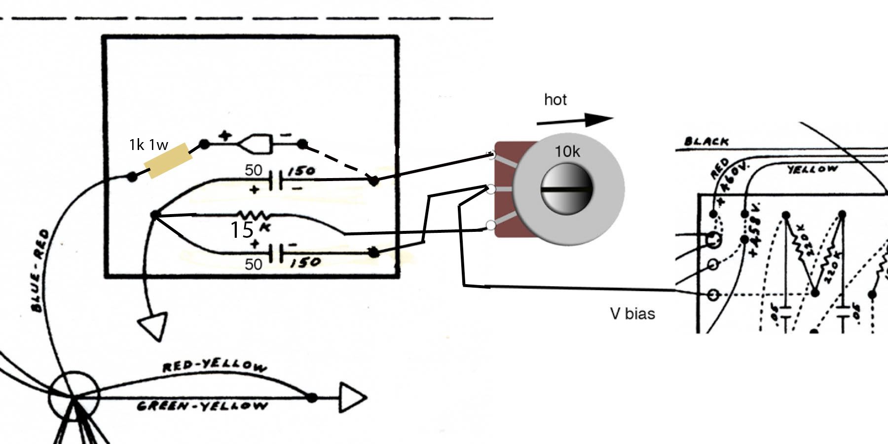
Or, if you have the small, single turn top adjust trim pot that fits snugly between the 10K eyelets on the board - remove the jumper under bias board from the bias diode to 10K, move the 8uf cap from the eyelet where jumper & 10k met & move to end of bias diode. Replace jumper with 1K resistor, replace 10K resistor with a 10-20K trim pot (still wired as a variable resistor). So now the 1K fixed resistor & trim pot are in series, 8uf cap meets the junction of the bias diode and 1K, other 8uf is as before. Most folks however would prefer to have the pot as part of the load, as adescribed previously.
Before installing tubes, set trim pot to maximum negative voltage at pin 5 of the power tubes (-61vdc approx?), then install tubes and fine tune current in mA.Comment
-
Yes, I'm assuming it's fixed bias - Thanks for the suggestions. I'll let you know the outcome.Comment
-
There seems to be a little confusion about the term "fixed bias". "fixed bias" means only that there is an external bias supply, either from a dedicated bias winding in the power transformer like your Concert or a tap off the high voltage winding suitably conditioned like a Princeton Reverb. Fixed bias can be either adjustable with a trim pot or somewhat less easily adjusted by swapping out resistors.Originally posted by gbono View Post
The other kind of bias is cathode biased, which is adjustable by swapping out different values of cathode resistor. It's generally considered to be less efficient but certainly easier to construct-no pesky external bias circuit to meddle with.Comment
-
Speaking of confusion - why does the Concery schematic (Super and Pro Reverb also) show no connection to pins 2/7 on the 6L6GC - the heaters are not connected??Comment
-
The heater connections are understood.Education is what you're left with after you have forgotten what you have learned.Comment
-
Correct. The 6G12 schematic diagram shows the 6.3v supply with the notation "To all heaters"Originally posted by Enzo View PostComment
-
6G12 and 6G4
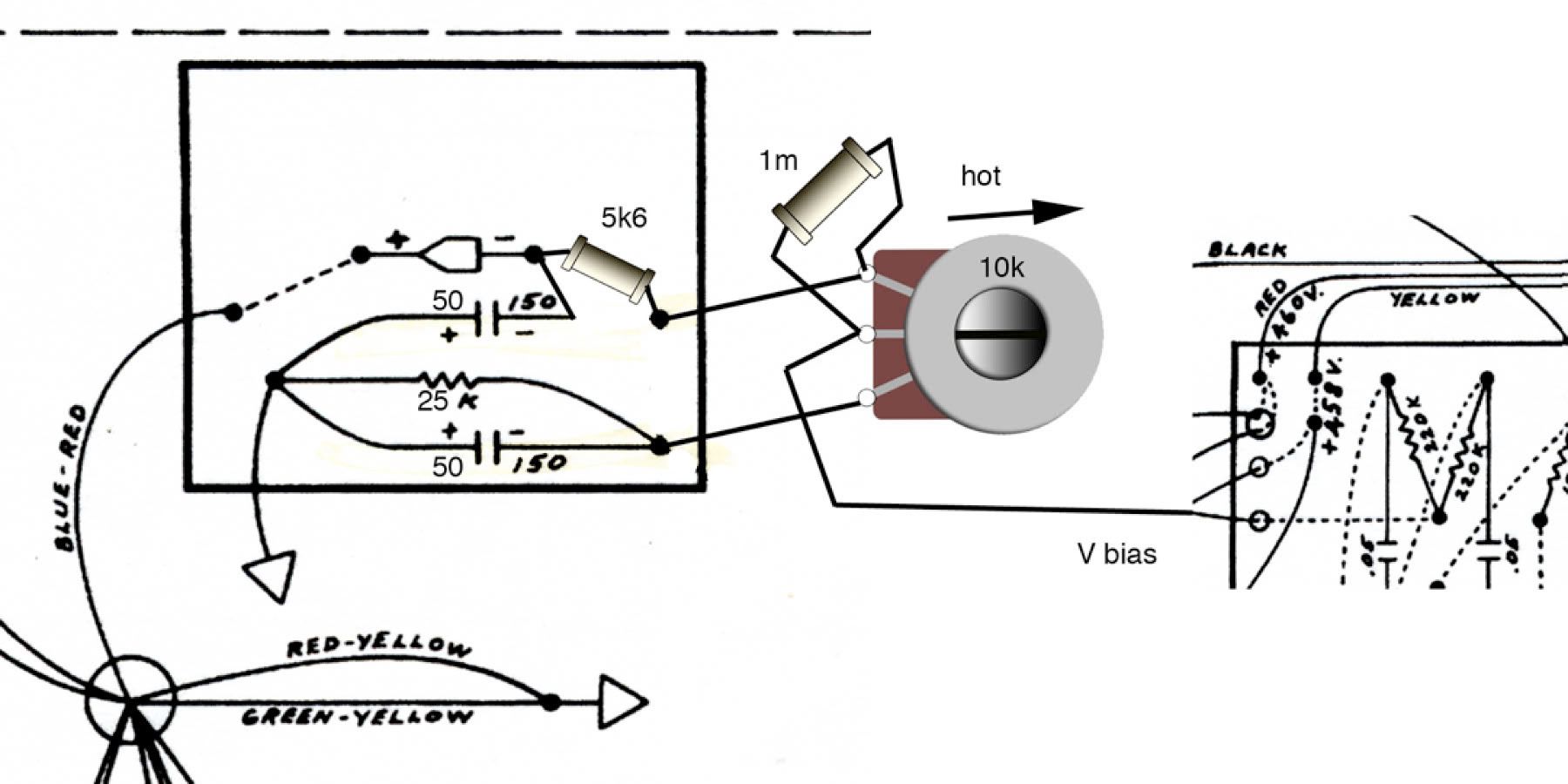
Hi it looks like both these amps have the same bias configuration. I am interested in the various ways that a bias pot can be added to the circuit.
The bottom pic represents the insertion of the piher small rectangular trimmer
in series.
My question is. Are these all viable. is there one better than the other. is there another approach.

Comment
Comment