Ad Widget

Collapse

Announcement

Collapse
No announcement yet.

When to start repair.

Collapse
X
 
  • Filter
  • Time
  • Show
Clear All
new posts

  • #16
    Often as not, when I have to pull a Mesa board, I demount the pots from the panel, flip them on top of the board sitting there. Pull any screws holding the board, then flip it up to expose the under side. I don;t unsolder rows of wires.

    Sometimes I find a board that only wants to come up part way - at an angle. Then I turn the amp over on its face or rear panel, whichever - and now I am looking down on a sloping board. Not unlike working on a Fender DeVille.
    Education is what you're left with after you have forgotten what you have learned.

    Comment


    • #17
      C'mon! wheres your sense of adventure?
      Hey now remember I do this with cars all day. lol
      Try pulling a head off a f150 without removing the cab.. Now thats fun.

      Looks like it's a vtl5c9 ldr. Dark resistance is 50m . Could I cut the ldr non led posts and "top solder" in a 50m resistor to test this thing out further?
      I would think this will just disable the half mode.
      I would hate pulling that thing out and have it not be the ldr.
      Thanks again.

      Ordered new tips for the Hakko last night if I need to reflow this thing I am going to do it right.
      Last edited by j.d.roost; 10-13-2009, 02:28 PM.

      Comment


      • #18
        Originally posted by booj View Post
        C'mon! wheres your sense of adventure? Pulling Mesa boards is not difficult. It just takes a little time. Just make a drawing of any wires you need to disconnect to get the board loose after you remove the knobs and loosen thier respective nuts. Be gentle, making sure not to force anything to happen, even if your only a 32nd of an inch away from getting it loose. Make a note of any ties you need to cut. The pots are a bit fragile, so take extra care with them. Have fun with it.
        Tag 'em and use that digital camera to take photos of everything.

        Comment


        • #19
          50 meg and open are about the same thing. I don't know how comfortable you are with probing around in a live circuit, or how accessible the leads are, but when the LDR is dark, there should be about zero volts between the angled side lead (neg) and the positive lead. When lit, that voltage should be about 1.6 vdc. I wouldn't try reading the on resistance with a meter with the circuit live because you would introduce DC voltage with the meter. The off resistance is very high, and the on resistance should be a few hundred ohms. Welcome to the world of Mesa switching circuits!

          Comment


          • #20
            I have no worries testing anything at this point.After spending two weeks with this thing open and on I feel a bit safer about all that voltage. Using the hand in pocket method and I have my probes attached to wooden dowels "just in case".
            I also bought a set of the small clips for my meter so I can attach one end to a resistor/ect. and still probe with one hand.
            I am fairly sure I checked the cell side (non angled) for voltage across it last night (too late if that was a no no) and think it was up near 65vdc.
            So there is voltage across it when the led is off (half mode not on).
            Guess I should test across that led/hit the half mode and look for the voltage
            change.

            Funny thing is I don't care about the half mode anyway.. I never use it.
            I have enough room in there to clip a post of the cell side and check it that way. I could just re solder it back together if I really needed to test it again.
            I don't think the Shack is going to have a 50m resistor..
            I did order two new ldrs from Allied today. They were only 7 bucks ea.

            Hey thanks again fo the help. I think I might be getting close to at least finding out whats wrong with this amp.

            Comment


            • #21
              Early this week I cut a leg off the old ldr and it effectively put the A channel into half drive (voltages on that tube shot up/down to spec.). I was able to play all week with no drop outs at all. My ldr's came in Thursday and I was able to top solder in the cell side (led side is going to call for a board removal ). This put the amp into full drive and it worked great all night long! Great it's fixed right....no.

              I turned everything on tonight and got a BUNCH of static/pops from the A channel. I hit a note on the guitar and it was back to 1/4 volume and all treble.. I hit standby and back on and the channel came back on for two hours of play time.
              So I would say its not fixed and would guess the new ldr is on the way out (there is a problem that is trying to burn it out and the new ldr is tough enough to keep the corresponding "bad part" under control for a bit.)
              At this point I know there is a problem before or after the ldr circuit but have no idea what it is. The ldr/feedback loop in the schematic has me pulling my hair out,I just don't understand how it all goes down.
              I don't know what else I can do with just a meter without pulling the board and doing a re-flow. Problem is I WANT TO PLAY...
              Ugh...towel is about to be tossed in.

              Comment


              • #22
                Originally posted by j.d.roost View Post
                Early this week I cut a leg off the old ldr and it effectively put the A channel into half drive (voltages on that tube shot up/down to spec.). I was able to play all week with no drop outs at all. My ldr's came in Thursday and I was able to top solder in the cell side (led side is going to call for a board removal ). This put the amp into full drive and it worked great all night long! Great it's fixed right....no.


                I turned everything on tonight and got a BUNCH of static/pops from the A channel. I hit a note on the guitar and it was back to 1/4 volume and all treble.. I hit standby and back on and the channel came back on for two hours of play time.
                So I would say its not fixed and would guess the new ldr is on the way out (there is a problem that is trying to burn it out and the new ldr is tough enough to keep the corresponding "bad part" under control for a bit.)
                At this point I know there is a problem before or after the ldr circuit but have no idea what it is. The ldr/feedback loop in the schematic has me pulling my hair out,I just don't understand how it all goes down.
                I don't know what else I can do with just a meter without pulling the board and doing a re-flow. Problem is I WANT TO PLAY...
                Ugh...towel is about to be tossed in.
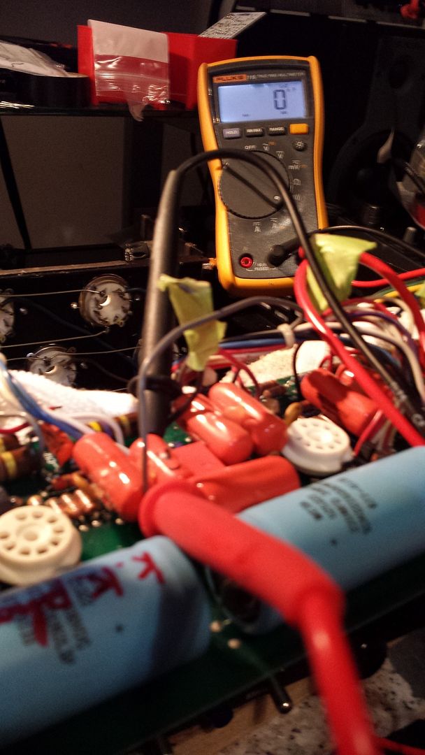
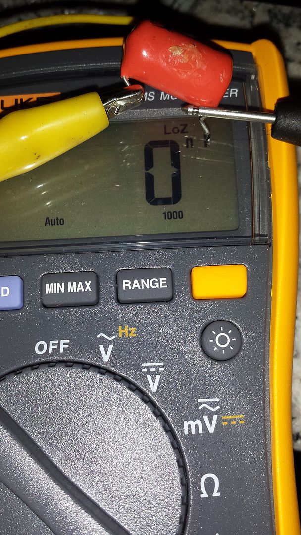
                Back from the dead. After giving up on this and buying a 50 50.. (Also after building 100 + pedals).. I decided to dive in and give it another go. After about 2 hrs. I had the PCB out..and started checking over things. Everything was close to spec. Untill I found the cap. That connects the volume pot to the grid of v3a. (C16) on schematic. I "think" this a coupling cap. Gonna recap it while it's apart. Hopefully the o.tranny for the a channel is ok. Going to school on this one.
                Last edited by j.d.roost; 04-28-2015, 03:27 PM.

                Comment


                • #23
                  A shorted orange drop! Well I never...seen one that is. Is the tube in the socket? I wonder how it tests "out of circuit".
                  Now Trending: China has found a way to turn stupidity into money!

                  Comment


                  • #24
                    ...

                    Comment


                    • #25
                      Originally posted by guitician View Post
                      A shorted orange drop! Well I never...seen one that is. Is the tube in the socket? I wonder how it tests "out of circuit".
                      No tube. Opposing cap on b side reads proper capacity in circuit (nice thing about having a stereo amp). But I will pull and test to rule out a pcb short ect.I can see why I had such a hard time finding somebody that wants to work on it. was an absolute
                      bear to get unsoldered from the chassis.

                      Comment


                      • #26
                        Does anyone have a readable schematic for this amp? It would be nice to know what parts you have been changing and what part of the circuit that they are in.

                        Comment


                        • #27
                          Originally posted by 52 Bill View Post
                          Does anyone have a readable schematic for this amp? It would be nice to know what parts you have been changing and what part of the circuit that they are in.
                          http://tubefreak.com/2901.gif
                          http://tubefreak.com/290pwr.gif


                          Not very readable...but that's all I could find.
                          Also...should I reflow all the solder joints or can that induce more problems than its worth?
                          Last edited by j.d.roost; 04-28-2015, 08:32 PM.

                          Comment


                          • #28
                            Yep....She no good..

                            Comment


                            • #29
                              Here's a copy.
                              Attached Files
                              Drewline

                              When was the last time you did something for the first time?

                              Comment


                              • #30
                                Just out of curiosity... Have you pugged in a cable from your effects send to your effects return and fr your pre out to main in if you have them to see if there is a difference. Also try using the pre out or effects send to drive another power amp or drive the amp from another preamp source into the effects return or main in to isolate if the problem is on your pre amp or output section.

                                Comment

                                Working...
                                X