What is the proper procedure for bringing up a tube amp on a variac, when amp has not been operated for a few years?Is this done over a few hour period?
What is the proper procedure for bringing up a tube amp on a variac, when amp has not been operated for a few years?Is this done over a few hour period?
"Proper" is probably not the right word here.
The only issue in bringing up an amp that hasn't been turned on for years is that the caps may have become leaky, and the sudden application of voltage *without a current limit* may cause the internal leaky spots to overheat, degrade, become leakier and run away, destroying the cap and whatever feeds it. The way to prevent runaway like this is to limit the current to the caps for the first few time units.
Use of a variac is an attempt to do this by limiting the available voltage so that the small resistances in the circuit will limit the current. I personally have always found this a clumsy process, like rebuilding a carburetor or soldering in SMD parts while wearing snow mittens. It can be done, but it takes concentration and practice to get it right. It also has a technical problem. If the unit being brought up has a tube rectifier, the tube rectifier won't start heating until the variac/line voltage is nearly normal. So the tube rectifier is preventing you from bringing up the line voltage at low levels because until it heats, nothing happens at all. The lower levels of AC line voltage from a variac cause nothing to happen at all.
I very much prefer putting a high resistance, perhaps 100K, directly in series with the cap, then putting full voltage on it. The 100K resistor limits the current even if the cap is so leaky to be almost shorted. At low currents, capacitors can rebuild the leaky oxides spots and get less leaky. It's when the current is too high that the spots run away. With a high resistance in series with the cap, you can simply apply full voltage, then measure the voltage across the resistor.
When that drops to less than 10% of the applied voltage (or when the cap voltage rises to more than 90% of the applied voltage, which is the same thing), then the cap is probably going to be fine with the full voltage across it. If you're an Ohm's Law cognoscenti, you'll recognize this criteria as meaning that the internal leakage resistance of the cap is bigger than 900K, so it's not very leaky. If the voltage on the cap never climbs over 90% of the applied, I personally would replace it. It's limping badly, and probably can't heal.
The PITA with this method is that you have to perform solder-surgery to install a resistor in series with the cap(s).
I notice I forgot to add: all the tubes other than the rectifier should be removed for the reforming. They'll just complicate things.
It's always something, isn't it?
Amazing!! Who would ever have guessed that someone who villified the evil rich people would begin happily accepting their millions in speaking fees!
Just gut the amp of all those electrolytic caps and replace them. They are bound fail eventually. Trying to save them is more trouble then it's worth. Besides, the amps caps have built in failure mechanisms.
Now Trending: China has found a way to turn stupidity into money!
The only issue in bringing up an amp that hasn't been turned on for years is that the caps may have become leaky, and the sudden application of voltage *without a current limit* may cause the internal leaky spots to overheat, degrade, become leakier and run away, destroying the cap and whatever feeds it. The way to prevent runaway like this is to limit the current to the caps for the first few time units.
Use of a variac is an attempt to do this by limiting the available voltage so that the small resistances in the circuit will limit the current. I personally have always found this a clumsy process, like rebuilding a carburetor or soldering in SMD parts while wearing snow mittens. It can be done, but it takes concentration and practice to get it right. It also has a technical problem. If the unit being brought up has a tube rectifier, the tube rectifier won't start heating until the variac/line voltage is nearly normal. So the tube rectifier is preventing you from bringing up the line voltage at low levels because until it heats, nothing happens at all. The lower levels of AC line voltage from a variac cause nothing to happen at all.
I very much prefer putting a high resistance, perhaps 100K, directly in series with the cap, then putting full voltage on it. The 100K resistor limits the current even if the cap is so leaky to be almost shorted. At low currents, capacitors can rebuild the leaky oxides spots and get less leaky. It's when the current is too high that the spots run away. With a high resistance in series with the cap, you can simply apply full voltage, then measure the voltage across the resistor.
When that drops to less than 10% of the applied voltage (or when the cap voltage rises to more than 90% of the applied voltage, which is the same thing), then the cap is probably going to be fine with the full voltage across it. If you're an Ohm's Law cognoscenti, you'll recognize this criteria as meaning that the internal leakage resistance of the cap is bigger than 900K, so it's not very leaky. If the voltage on the cap never climbs over 90% of the applied, I personally would replace it. It's limping badly, and probably can't heal.
The PITA with this method is that you have to perform solder-surgery to install a resistor in series with the cap(s).
I notice I forgot to add: all the tubes other than the rectifier should be removed for the reforming. They'll just complicate things.
It's always something, isn't it?
Agree about the rectification issue, RG. I saw this in action when I was bringing up a 1934 vintage Majestic table radio. Nothing until the variac reached about 70v, then the rectifier started working and I had about 70 per cent of normal B+ right then and there.
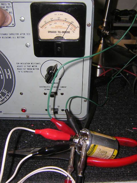
As far as reforming goes I'm experimenting with a couple NOS 20/20/20/450 FP type can caps I have. I use my Sprague TO5 Telohmike to reform them, all the while keeping the leakage below 0.5 ma and monitoring temperature. It took about a day.
That is one reason I have a Sovtek solid state rectifier plugin here. You can also make one out of a tube base and some diodes too.
Thanks guys, your info gives me some direction which to go and that is a big help now. We all have to start somewhere. This is a Bogen chb100 and looks new, just been in storage a few years. I don't want to tear it apart or just power it up so I have access to a variac and will give it a try. Thanks again, Rayme
Just gut the amp of all those electrolytic caps and replace them. They are bound fail eventually. Trying to save them is more trouble then it's worth. Besides, the amps caps have built in failure mechanisms.
Would you like to have the discussion again?
Amazing!! Who would ever have guessed that someone who villified the evil rich people would begin happily accepting their millions in speaking fees!
Hopefully this isn't to far off topic but I've been studying DC/AC inverters for the photovoltaic industry. Here are two papers on electrolytic capacitor reliability. Though this relates to "micro-inverter" technology - typical or traditional grid tied inverters must reliably deal with 600 VDC (over 1000 VDC in europe) with 10's of amperes of current.
Guitar amp duty is pretty easy, compared to the punishment capacitors see in switchmode power electronics. Unless the cap is mounted too close to some hot tubes, that'll kill it just as quick as internal heating from ripple current would.
"Enzo, I see that you replied parasitic oscillations. Is that a hypothesis? Or is that your amazing metal band I should check out?"
Today Scotland appears to be using much more wind (tide?) RE than solar. I assume that this is due to solar path and weather there??
Yes, heat is the big problem with aluminum electrolytics - I have to believe that is why you see 35 year old filter caps still functioning in some solid state designs (at least the ones with good thermal management of PS and output devices). Also easier to de-rate the cap's WVDC on a supply rail that is under 500V
gbono: Solar power in Scotland, lol. There just isn't enough sunshine, PV modules have a payback time of about 25 years at current electricity prices.
My PhD project was a dispatching system based on a virtual market, and when I turned it on, it refused to use any of the renewable power because it was too expensive. I had to program in a hefty subsidy. :-)
"Enzo, I see that you replied parasitic oscillations. Is that a hypothesis? Or is that your amazing metal band I should check out?"
I'm glad your Bogen is still living the good life. I had a K10 and K15 and they were great amps. Picked them up at a flea market in the mid '80's for $10 ea. I remember just plugging them in after making an adapter for the XLR connectors and thinking WOW.....who knew this would sound so good....it's not a guitar amp! I think I grabbed it because of the Chicago album credit of "Utilizing a Bogen PA as a pre-amp" for "Free Form Guitar".
The caps were never an issue with them. I do remember they used a phenolic mounting for the multi-cap can, which helped keep the cap cool.
Now Trending: China has found a way to turn stupidity into money!
 Tweet
Tweet


")

Comment