Ad Widget

Collapse

Announcement

Collapse
No announcement yet.

Can you guys help me understand what happened here?

Collapse
X
 
  • Filter
  • Time
  • Show
Clear All
new posts

  • Can you guys help me understand what happened here?

    I'm in the process of learning electronics and amps. Slow process due to time available, but it's enjoyable. I have a problem that's cropped up and am hoping someone can help me understand what's happened.

    I bought a 1974 Fender silver face Champ at a guitar show a couple months ago. It worked fine for a few hours, then started malfunctioning.

    At the time I was told about three capacitors that where replaced (and given the originals). These turn out to be the three cathode bias caps. I've since found out the 1Meg volume pot has also been replaced. That's where the trouble started, I think.

    For the first couple hours, the amp worked fine. At some point I started to get volume drops, it started making some popping and cracking noises, and I shut it down because I could tell something was wrong.

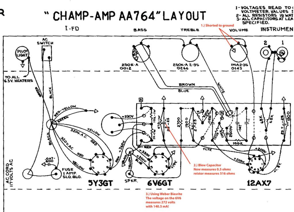
    So, I pulled the chassis and had a look. This is when I could see the volume pot had been replaced. Whomever did it was pretty sloppy. They'd used a (I assume) non stock shielded single conductor wire to run from pin 7 of the 12AX7 to the volume pot's center lug. They did not connect the sheild at the tube end, but soldered it to the ground lug at the volume pot end. There was such poor lead dress that the sheild wire effectively shorted the input and the ground lugs of the pot.

    I fixed this and put it all back together and fired it up once more. The popping and crackling was still there, then I heard one loud pop and saw a bit of smoke coming from the unused input jack. This was a "oh shit" moment for sure. I was getting no signal shortly afterwards.

    So, for reasons I can't explain other than idle stupidity, I installed a new rectifier tube and fired it up. The rectifier and the pre-amp tube both glowed (heater's working), but not the power tube. I replaced the power tube with a known good and now the amp worked. It did not sound it's best, but there was no noise that shouldn't have been there (like popping and cracking). I played through it for a bit and noticed the power tube was red plating, especially when I wasn't playing, or playing at low volumes. When I cranked it up and wailed on some barre chords, it wasn't redplating.

    Hmm, so I got out my Weber biasrite and plugged it in between the 6V6 and the tube socket. It read 272 volts and 140mA! Geez, no wonder it's red plating and the previous (new) power tube had failed.

    So I took the chassis back out and started inspecting. It was then I noticed the 22µF/25volt cathode bias cap had literally blown up and shot it's stuffing out one end. The plastic wrapper was also somewhat melted on the same end. I removed this and the 1 watt 470ohm resistor and measured them both. The resistor measures 516 oms and shows no evidence of being overheated. The capacitor actually measures 0.5 ohms. So effectively, my cathode bias went from around 500 ohms to 0.5 ohms.

    I think I can now understand why my Weber was showing 140mA. But, did that cap blow because of the shorted volume pot, or should I be on the lookout for other issues as well?


  • #2
    Cathode Bypass capacitor

    I do not think shorting the volume pot caused the 22 uf cap to blow.
    Afterall, isn't that what the pot does when you turn it full CCW?

    Comment


    • #3
      Originally posted by Jazz P Bass View Post
      I do not think shorting the volume pot caused the 22 uf cap to blow.
      Afterall, isn't that what the pot does when you turn it full CCW?
      Excellent point!

      Comment


      • #4
        The cap was either put in backwards or was getting overvoltage. You should measure the voltage at the Cathode above the resistor and measure what it is. Also measure the Cathode resistor and make sure it is reading the correct ohms. FWIW these amps run Class A and dissipate over 100% during full power so you will burn up a tube quicker than normal.
        KB

        Comment


        • #5
          Originally posted by Amp Kat View Post
          The cap was either put in backwards or was getting overvoltage. You should measure the voltage at the Cathode above the resistor and measure what it is. Also measure the Cathode resistor and make sure it is reading the correct ohms. FWIW these amps run Class A and dissipate over 100% during full power so you will burn up a tube quicker than normal.
          Pretty sure the cap was installed correctly...negative was connected to the ground side of the fiber board, positive to the wire going to the tube socket, pin 8.

          The resistor measured 516 ohms, so that was within 110% of specified.

          I suspected the cap is/was getting overvoltage, and need to measure before the cathose resistor, as you say. I'll be doing that this evening. I'm just wondering what caused it, so I can prevent this happening again.

          I'm thinking there's a problem with either the 5Y3 (which was original and has now been replaced) or the cap can and thus the screen grid voltage....

          Comment


          • #6
            I think you have the chicken or the egg question here.

            Did the cap short and take out the power tube or did the tube short and take out the cap? Either way, replace the power tube, the cathode resistor and the cathode cap.

            One other point, when using shielded cable for input grid lines or any line for that matter, you should only ground the shield at one end. Grounding at both ends can cause ground loops and hum.

            Comment


            • #7
              Cathode resistors for power tubes get hot, a 25v cap is a little under rated, use a 25uf/100v cap, keep it elevated above the resistor (or vice versa), your cathode resistor has drifted, replace it with a 5W type - SF champs run the 6V6 at over 20W dissipation with 470ohm, they can take this but you might also like to try 680ohms (16-18W?) or 800ohms (14-15W?) value.

              What's wrong with your screen grid voltage? SF Champs often run the screen grid a little over the plate voltage, not ideal but it is the norm.

              Replace the cap can (or leave in place to preserve original look & mount new caps in the chassis), use individual caps, 500v rating, 40-50uf for the main B+, 20uf for the screens, 20uf for the preamp. Ground main & screen caps to a PT bolt, ground the preamp cap to #1 input jack ground lug.

              Comment


              • #8
                Use a 50v cap on the pwr tube's K bypass. I have a 70s champ on the bench right now and the K voltage is over 25v. This will vary with different 6V6 varieties and the *actual* value of the K resistor.
                The farmer takes a wife, the barber takes a pole....

                Comment


                • #9
                  First off, thank you gentlemen!

                  Originally posted by Gtr_tech View Post
                  Use a 50v cap on the pwr tube's K bypass. I have a 70s champ on the bench right now and the K voltage is over 25v. This will vary with different 6V6 varieties and the *actual* value of the K resistor.
                  This makes much sense to me. I've first hand experience with how different tubes effect bias levels and can completely understand how this could have been the root cause...

                  Originally posted by 52 Bill View Post
                  Did the cap short and take out the power tube or did the tube short and take out the cap? Either way, replace the power tube, the cathode resistor and the cathode cap.
                  Yes, chicken or egg? Totally get that now and think it's the crux. I will replace the cap, tube and resistor this evening and take some voltage readings to see if all looks well.

                  And thank for the recommendation up upping the cathode bias cap's voltage spec. I think I'll start with 50 volts and see how that holds up.

                  And thanks for the note about shielded cable...that's jibes with what I've read elsewhere and why I left it as is, once I corrected the lead dress.

                  Originally posted by MWJB View Post
                  Cathode resistors for power tubes get hot, a 25v cap is a little under rated, use a 25uf/100v cap, keep it elevated above the resistor (or vice versa), your cathode resistor has drifted, replace it with a 5W type - SF champs run the 6V6 at over 20W dissipation with 470ohm, they can take this but you might also like to try 680ohms (16-18W?) or 800ohms (14-15W?) value.
                  Makes sense they'll get hot....and also explains why it was elevated off the board quite a bit.

                  I'm thinking of using a metal film instead of carb comp for the replacement, as it's not directly in the signal path. I'll go with stock value and 5W to start and monitor from there.

                  The other mods you mention all make sense, but I'm going to start simple and see how the circuit reacts. I had no extraneous noise before things started to go south, so if the voltages look good after replacing the cap/resistor/tube, then I might stop there.


                  Again, thank you gentlemen! I will try to come back and update with my findings so the info is archived.

                  I'm getting the parts this evening after work and if my luck holds, the place I shop will have some NOS tubes I can pick up as well. He's often got some behind the counter.

                  Comment


                  • #10
                    Zener diode protection

                    FYI
                    I have seen, on newer amps, where a 56 volt zener diode is inserted in parallel (anode to ground) with the cathode resistor/ bypass cap. Part# 1N5370B.
                    It helps prevent the capacitor from exploding if the output tube should develop a short. (Huh, imagine that)
                    Some sort of NEMKA safety requirement.
                    Cheers.
                    Attached Files
                    Last edited by Jazz P Bass; 11-19-2009, 06:03 PM.

                    Comment


                    • #11
                      Most likely scenario is the first power tube failed, shorting a high voltage element to the cathode. That blew up your cap. Now that the cap is shorted, your new good tube will red plate. Pops and crackles is usually a sign of a failing power tube.
                      Education is what you're left with after you have forgotten what you have learned.

                      Comment


                      • #12


                        OK, got the new cathode cap and resistor installed last night. Had to go with what I could get locally after work. That was a 470ohm 2 watt metal film and a 22µF 62 volt electrolytic. I installed these with a NOS TungSol 5Y3GT, NOS TunSol 6V6GT and a NOS TungSol 12AX7.

                        Hooked up my Biasrite and got 363 volts and 53.5 mA.

                        I took voltages at all the points specified on the schematic shown above. Mine are in red.

                        I don't think these tubes will live long in this environment. The voltage on the 6V6 is OK, but the current draw is about 50% higher than it should be.

                        While the schematic says voltages listed are +/- 20%, and many of mine fall within that, I still don't like that this little amp is being fed 400 volts when it should be down around 360.

                        The tube is not red plating, but the cathode is glowing awfully bright...sound wise, it's livable but not much headroom and a touch harsh.

                        Can I do anything about this? I plan to replace the three 20µF filter caps with 450 or 500 volt new ones, as well as replace the dropping resistors (which I have not measured yet). Could I stick a 10K 5 watt resistor between the rectifier and first filter cap to drop this down closer to 360 volts?

                        Comment


                        • #13
                          It would be valid to put in a dropper resistor after the rectifier in order to get the voltages and 6V6 plate dissipation to lower levels, but around 680ohms 5-10 watts would be a better choice. With resistors, it's best to check for their 'limiting element voltage' and ensure that it's within the max instantaneous level it will likely see, ie at switch on. Some might be as low as 200V, which won't cope with many switch on cycles (in this application). Peter.
                          My band:- http://www.youtube.com/user/RedwingBand

                          Comment


                          • #14
                            "I don't think these tubes will live long in this environment. The voltage on the 6V6 is OK, but the current draw is about 50% higher than it should be." No it's not, it's fine. 19.4W is less than I have seen in other SF Champs...many of which have had the same 6V6 for a decade or more...

                            When you find a SF Champ that actually runs 360vdc after the rectifier, with original value cathode resistor, PT etc & good caps, let me know...I'll eat it (I am that sure that you will never find one)!

                            Your voltages are "typical" to "low side of typical". You don't have a problem....just a SF Champ.

                            a 10K resistor between rectifier & first flter cap will kill the tone & make the amp raspy & wheezy. If you really want to drop the B+ (I don't think it's a good idea, but it's your amp) use reverse polarity zener diodes between PT B+ centre tap & ground.

                            If you really don't like the sound of the amp at all, it's probably best to sell it & buy something else.

                            Comment


                            • #15
                              Actually, I love the sound of the amp. When I got the voltage readings I intended to only play for about 5 minutes and then shut her down and see what you guys had to say....that 5 minutes turned into well over an hour!

                              I got the 6V6 for $25, plus a spare, so maybe I'll just see how long it lasts...or put a new production JJ in it....I might also try the recommended dropping resistor for the hell of it...

                              In any case, I thought 50mAmps power draw through the tube was crazy high, but if it's not, then good deal.

                              Thanks for all your help!

                              Comment

                              gebze escort kurtköy escort maltepe escort
                              pendik escort
                              betticket istanbulbahis zbahis
                              deneme bonusu veren siteler deneme bonusu veren siteler
                              casinolevant levant casino
                              Working...
                              X