Announcement

Collapse
No announcement yet.

Acoustic 125 guitar combo issues.. no output!

Collapse
X
 
  • Filter
  • Time
  • Show
Clear All
new posts

  • Acoustic 125 guitar combo issues.. no output!

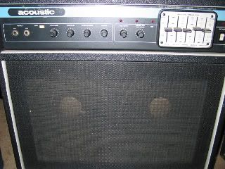
    This is an old late 70's Acoustic 125. Great sounding amp but hasnt worked in quite some time and I wanna get it back together. Speakers are okay (tested w leads from another amp) but theres no output from the actual amp.

    I ran a cable from the preamp out to my effect return in my classic 30 and got a strong clear signal, the EQ sliders were functioning and tone/volume controls worked (Master Volume was not engaged - problem w footswitch as well.). Slight hum but that could either be from 1. old amp plugged into same outlet as computer and other amp that signal was being sent to 2. whatever issues the output stage has could be makin the hum..

    Any help greatly appreciated. This was a gift from my uncle when I first started playing. THanks in advance.


  • #2
    Acoustic 120

    You might want to try to locate a schematic.
    Tha Acoustic amps are a wiring nightmare.

    Comment


    • #3
      acoustic 125.. slight update.

      Well, opened it up.. I guess when my uncle had it something happened and he decided to cut the leads to the power section. Also looks like a component is missing, not sure what without a parts list.

      I do have to say, I slightly disagree with the wire nitemare part. This amp looks quite linear and Acoustic's use of colored wires makes it easy to see whats goin where. Its like a rainbow inside this thing..lol

      So now that I realized the Preamp's fine but the 170080 power section just needs a lil work, the main goal is getting the parts list and schem for this.. but havin a hell of a time finding one. HELP!!

      Here's some inside pics.


      Comment


      • #4
        Acoustic 125 schematic

        Here is a link.
        You will have to buy it.
        Link:Acoustic Schematics

        Comment


        • #5
          The left side of the board connects with jumpers to the 4 large output transistors on the center heat sink. The right side wires connect to the power supply and the preamp.

          Having the schematic will help you in figuring this out.

          I'd start by checking the 2 driver transistors on the board, the ones with the built in heats sinks, as they will be the hardest parts to source.

          Comment


          • #6
            Its not the leads or transistors that are the problem, I tested those. Look at the pic of the board. There's something actually missing that was attached to the PCB. the leads and solder r still there but it had to have been some big capacitor or something that must've blown up. Thats the part I need to find. its the only thing keeping this amp from working.

            Comment


            • #7
              Missing component

              Can you do some voltage, continuity checks.
              Where that missing part was, it looks like two identical circuits around those heat sinked transistors.
              What is the purpose of these two circuits.
              + - 15 volts?
              Flip the board over. Where do the "missing component" traces go?
              Is one of them at ground?
              Is there any voltage on the leads?

              Comment


              • #8
                Originally posted by Jazz P Bass View Post
                Can you do some voltage, continuity checks.
                Where that missing part was, it looks like two identical circuits around those heat sinked transistors.
                What is the purpose of these two circuits.
                + - 15 volts?
                Flip the board over. Where do the "missing component" traces go?
                Is one of them at ground?
                Is there any voltage on the leads?
                The two heat sinked transistors on the board are the drivers RCA 40409 and RCA 40410.

                Comment


                • #9
                  Missing component traces

                  Quote:Flip the board over. Where do the "missing component" traces go?
                  Is one of them at ground?
                  Is there any voltage on the leads?
                  Any chance that you could answer this.
                  You have the amp, we don't.
                  Without more info we are dancing in the dark.

                  Comment


                  • #10
                    Feedback

                    It might be for a feedback capacitor.

                    Comment


                    • #11
                      I just spent 3 days trouble shooting an Acoustic model 123 without a schematic - good luck. BTW, I broke down and bought a schematic for this model from MusicParts it was 3 revisions behind the board design I had - useless.

                      The main problem I had was keeping track of all the leads that were breaking when I had to move PCBs. I thought this was ironic since Acoustic used edge connectors on their earlier designs (150, 140, etc).

                      Your picture is pretty blurry.....

                      Comment


                      • #12
                        Is your driver board the 170074 or the 170080?

                        It appears the black wire is ground for power supply and speaker, the red wire is the V+ from the power supply. The orange wire is the output to speaker. The input ground is black with white stripe, and the input signal is green. That work with your wires?

                        I suspect you have the 170074 (possibly written 17-74), since the circuits are about the same, but the 170080 has the edge connector terminations on the end of the board. Your board lacks that apparently.

                        Has the large cap vented? Looks like cap spooge out the top end of it.
                        Attached Files
                        Education is what you're left with after you have forgotten what you have learned.

                        Comment


                        • #13
                          170080 power board,

                          its the 170080.

                          Comment


                          • #14
                            i apologize for the blurry pics.. cams on the fritz.

                            nothing like a really expensive Canon to give the best blurry pics for the $$...oy.

                            Anyway, theres definitely signs that something blew up on this board. Whatever that thing is thats missing with its two cut leads still attached to the board and remaining solder. Right next to the missing * is a small black component with lettering on it reading:

                            FPN
                            2484
                            EBC

                            It has 3 leads coming out of the bottom of it (well used to, the one side blew out and the 3rd leg is hangin freely) This is on the board to the left of the Heat sunk RCA transistors..

                            Im gonna post some more pics here (sorry if they are blurry, this cam stinks) & hopefully someone can identify whats there and whats not.

                            Comment


                            • #15
                              The blown apart guy on the end is your bias transistor. And that agrees with the schematic.

                              Wow, my scan was really crappy, I'll try to find a better one.

                              The missing part is probably the 0.24 ohm 7w output ballast resistor R26.
                              Education is what you're left with after you have forgotten what you have learned.

                              Comment

                              Working...
                              X