 Tweet
Tweet
I have a marshall jtm clone that I recently modded. Originally the new bias circuit was tapped at unknown voltage. However this caused redplating after a few minutes, regardless of bias position. Thinking there was too much negative voltage, I retapped the bias closer to 0. Now the tubes redplate at turn on, and the fuse blows almost immediately. Am I to assume I should tap at a lower voltage (away from ground)?
-
-
You are travelling the wrong way.
Your original bias was not enough, causing redplating.
If you lower it ("going closer to 0"), you will redplate even more.
What is your actual bias voltage?
Post the schematic of what you did.Juan Manuel Fahey -
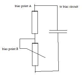
bias point B was where extreme redplating happened immediately
bias point B is where i have reset the bias too
bias voltage at grids is about -34V
grids no longer redplate, not even a little (although this is under no input signal)
i unhooked the ground for the tubes, and measured idle current
based of plate voltage, 100% bias would be
25w/464v= .053A 70% being .037A for a single tube
measured the current both tubes, assuming i would get twice that value, or .075A. however, i was astounded to find i was getting .144A
after some rechecking of my wiring, i realized one of the grids was wired to ground (pins 1/8 which is correct according to the schematic). am i correct to assume that since i measuring current from plate through cathode (which should be 0 volts) as well as plate through that third grid (pin 1 or 8, forgot which one its actually connected too) i would get 4 times what i should get per tube? (double the amount since im measuring both tubes, and then doubled again for measuring through the grid as well)?Comment
-
Hi ionsandpylons,
Your schematic doesn't help me very much because it has no info.
No component values, no voltages, no connections to external elements.
Please redraw at least the output pair of valves (all their pins), their connections to supply, bias, output transformer, etc. and the full bias circuit, stating the grid voltage with the bias preset at max. , min. , and middle positions.
Your -34 volts are at least closer to what you need, we still need more consistent (and safer) current measurements, just unhooking the cathode and putting your multimeter in series is *dangerous*.
Good luck.Juan Manuel FaheyComment
-
Pull the power tubes and set them aside.
Turn on the amp and measure the B+ voltage at the plate and screen pins of the power tube sockets. And measure the bias voltage at the grid pin of the power tube sockets. WHat range ov voltages does your bias control provide there?Education is what you're left with after you have forgotten what you have learned.Comment
Comment