 Tweet
Tweet
Hey all,
I'm working on a sound city L100W. Poor thing looks like a monkey with a soldering iron got into it. I have a very strong suspicion that it is this very same amp from this thread:
http://music-electronics-forum.com/t17257/
anyways, burnt up screen resistors, terrible tube socket wiring... The OT tap to one set of EL34's was not even soldered, and making intermittent contact. Bias supply was all wonky. 10 amp(!!) mains fuse. Chopped up vacuum cleaner power cord, etc. There looks like there was a bunch of work done, and NOT done well.
I thought it was funny that someone spent a bunch of money on a shiny new Heyboer PT, and then did such a terrible job on all the other stuff.
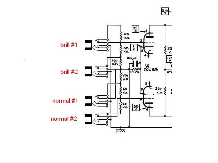
Anyways, if you read the thread above, you'll note that this circuit isn't stock, and I would like to return it to somewhat original shape. For reference, here's the schematic:
http://www.soundcitysite.com/sc_webpages/B100_schem.jpg
My question pertains to V2....
1) Is that really a 10k anode resistor? I know it is shared between the 2 halves of the tube, but it seems way too low for there. I have dug around without a clear answer, but I did find a few pics here:
J-Flats.com: Click image to close this window
showing a 220k (which is what is in mine). I looked for other gut shots, but they were all to small to see clearly.
2) Is the resistor on the last B+ tap 68k(the one feeding the input tube stage anodes through the 220k's)? Mine has a 10k in there now, again way off.
Anyways, with all that stuff wrong, it still sounded decent before I unbuttoned it to look. As soon as I pulled the chassis, my eyes popped.... Slightly scorched EL34 socket, replaced bias pots, and all the other goofy "mods".
I'd be so appreciative of anyone with a L100w that could help me out by letting me know the value of those 2 resistors in their amp.
thanks much
-Morgan
I'm working on a sound city L100W. Poor thing looks like a monkey with a soldering iron got into it. I have a very strong suspicion that it is this very same amp from this thread:
http://music-electronics-forum.com/t17257/
anyways, burnt up screen resistors, terrible tube socket wiring... The OT tap to one set of EL34's was not even soldered, and making intermittent contact. Bias supply was all wonky. 10 amp(!!) mains fuse. Chopped up vacuum cleaner power cord, etc. There looks like there was a bunch of work done, and NOT done well.
I thought it was funny that someone spent a bunch of money on a shiny new Heyboer PT, and then did such a terrible job on all the other stuff.
Anyways, if you read the thread above, you'll note that this circuit isn't stock, and I would like to return it to somewhat original shape. For reference, here's the schematic:
http://www.soundcitysite.com/sc_webpages/B100_schem.jpg
My question pertains to V2....
1) Is that really a 10k anode resistor? I know it is shared between the 2 halves of the tube, but it seems way too low for there. I have dug around without a clear answer, but I did find a few pics here:
J-Flats.com: Click image to close this window
showing a 220k (which is what is in mine). I looked for other gut shots, but they were all to small to see clearly.
2) Is the resistor on the last B+ tap 68k(the one feeding the input tube stage anodes through the 220k's)? Mine has a 10k in there now, again way off.
Anyways, with all that stuff wrong, it still sounded decent before I unbuttoned it to look. As soon as I pulled the chassis, my eyes popped.... Slightly scorched EL34 socket, replaced bias pots, and all the other goofy "mods".
I'd be so appreciative of anyone with a L100w that could help me out by letting me know the value of those 2 resistors in their amp.
thanks much
-Morgan
Comment