Announcement

Collapse
No announcement yet.

Why did my amp blow up?

Collapse
X
 
  • Filter
  • Time
  • Show
Clear All
new posts

  • Why did my amp blow up?

    Hi All,

    I built a SE amp with a 6CA7 output tube that I've been asking many questions about in some other sections. I thought that it was nearly finished tweaking, and took it over to friends to test/compare with some other amps.

    He was playing at full output (or close to) for ~ 15 minutes when the sound started chopping out momentarily when he hit a chord. This happened for ~ 3 seconds, then there was a flash in the base of the 6CA7, and all went quiet except for hum. I very quickly turned the amp off, then turned it over to inspect the innards.

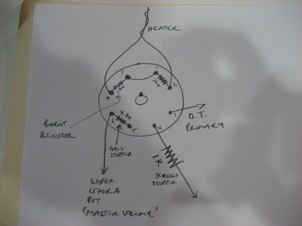
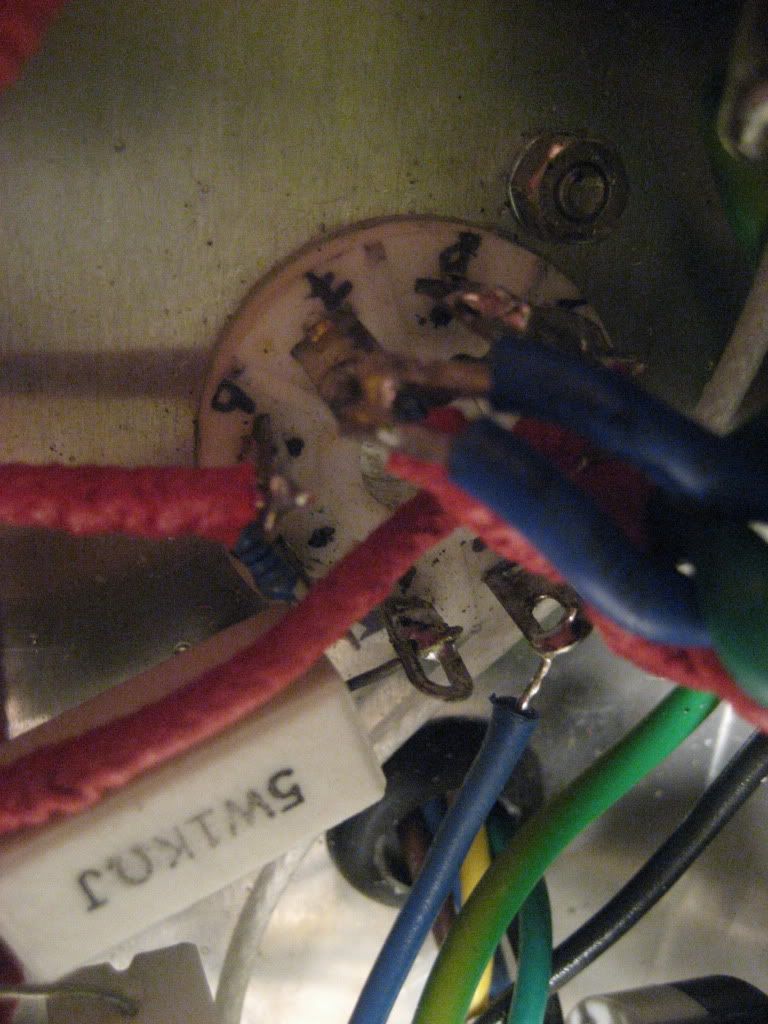
    There was a slight puff of smoke inside, but the only component that is visually damaged is one of the 2 * 100R 1/2W resistors that are creating the false heater centre tap, and also DC elevating the heater from the 6CA7 cathode bias voltage (cathode bias). The resistor that cooked was on the tube socket, wired between pins 8+1 (cathode and suppressor grid) and pin 7 (one of the heater pins).

    I very quickly used my knuckle to check some other components for heat, nothing else (first dropper resistor/sreen stopper/cathode resistor/transformers) were at all hot.

    Now in the Theory and Design section we have been discussing safe plate dissipations for tubes, this one was biased at idle for Pp = 24W, the specified max for this tube is 25W. There was no visual sign of the plate getting hot/glowing before the failure. Also from my very limited understanding of this stuff, the plate should have been running cooler running at full output than at no output.

    B+ = 328V. There is a 470R 5W first dropping resistor, followed by a 1KR 5W screen stopper. Is at idle = 10.0mA, Vs at idle = 310V.

    Also, heater voltage = 6.0VAC. 6CA7 grid leak resistance max. = 470K (a 470K potentiometer). OT primary 4K impedance.

    Any ideas for what went wrong?

    Cheers

  • #2
    Sounds like the tube shorted its HT to the heater.

    Comment


    • #3
      "The resistor that cooked was on the tube socket, wired between pins 8+1 (cathode and suppressor grid) and pin 7 (one of the heater pins)".Are you saying you had the resistor connected "between" pin 8 and 1,and then to pin 7?Or do you mean connected to pins 8 and 1 which are connected together,and then to pin 7?If you are using pin 1 as if it had no internal connection like in a 6L6,that would be a problem.In a 6CA7 pin 1 is internally connected to the suppressor grid,which,in a 6L6 is connected to the cathode,but has no pin connection.

      Comment


      • #4
        Thanks Alex R and stokes.

        Stokes - as the 6CA7/EL34 do not internally tie the supressor grid and the cathode together, I have them tied toghether with a wire link on the tube socket. The resistor is then from this point to heater pin 7.

        Alex R - Is this a normal thing for tubes to do when they fail?

        Comment


        • #5
          Can you show us a schem of how your heater supply and power tube socket is wired?

          Chuck
          "Take two placebos, works twice as well." Enzo

          "Now get off my lawn with your silicooties and boom-chucka speakers and computers masquerading as amplifiers" Justin Thomas

          "If you're not interested in opinions and the experience of others, why even start a thread?
          You can't just expect consent." Helmholtz

          Comment


          • #6
            Originally posted by jimboyogi View Post

            Alex R - Is this a normal thing for tubes to do when they fail?
            I dont know if it's 'normal', but I repaired a friends Bandmaster that had a tube short and it burnt the 100 ohm heater CT resistors.
            "In theory, there is no difference between theory and practice. In practice there is."
            - Yogi Berra

            Comment


            • #7
              I don't know how normal it is either but it can happen. All it takes is one internal arc and the HT can short to everything in there that isn't HT... I guess... anyhow, yep, those resistors often burn, and it ain't 6.3vAC doing that.

              Comment


              • #8
                Originally posted by Chuck H View Post
                Can you show us a schem of how your heater supply and power tube socket is wired?

                Chuck
                Here is a schematic and a photo. Note the multiple heater wires, the PT has two 6.3V heater windings, rather than snip one set off I wired them both up in parallel to the power tube socket, then ran the preamp heater wires from here.


                Comment


                • #9
                  So what's the plate current, 75-80mA? That's a lot, 24W plate dissipation is pushing it for a 6CA7 even at that low plate voltage. 60mA-ish is more typical, rarely over 70mA...& even then there might be some tubes that can't take it. I'd be loath to use a cathode resistor of less than 330ohms...more usually 470ohms if B+ is nudging 400vdc (at that value).

                  Comment


                  • #10
                    Originally posted by MWJB View Post
                    So what's the plate current, 75-80mA? That's a lot, 24W plate dissipation is pushing it for a 6CA7 even at that low plate voltage. 60mA-ish is more typical, rarely over 70mA...& even then there might be some tubes that can't take it. I'd be loath to use a cathode resistor of less than 330ohms...more usually 470ohms if B+ is nudging 400vdc (at that value).
                    Hi MWJB, you warned me didn't you

                    Yeah it was running nearly 78mA Ip with the 220R cathode resistor for 24W diss., or 68mA Ip with a 270R for 21W dissipation.

                    Thanks for your replies everyone, I'm starting to get the feeling that what happened was merely the tube blowing due to over-dissipation, and that is fairly easy to prevent going forward with a bigger cathode resistor as you point out MJWB

                    Comment


                    • #11
                      Last night I reworked the amp, replaced the 2 *100R resistors (they were both blackened and bubbly on the surface, but both still measured 98 ohms resistance!). Swapped the 220R cathode resistor for a 270R .
                      I checked all of the OT windings resistances, powered up without the tubes, checked voltages, inserted tubes, checked voltages, plugged in and all seems fine, hopefully it was just the output tube arcing from HT to cathode or heater that caused the trouble.

                      I also measured resistances across all of the pins on the 6CA7 that flashed, wondering if it had developed any shorts internally. Only the heater gave a reading, so no sign of shorts. All of the internal connections from the pins to the internal elements look intact also.

                      What causes a tube to arc like this under reasonable HT, with no sign of excessive temperature/red plating, or any internal shorts

                      Comment


                      • #12
                        Originally posted by jimboyogi View Post
                        What causes a tube to arc like this under reasonable HT, with no sign of excessive temperature/red plating, or any internal shorts
                        Dunno but it's a common failure mode.

                        Comment


                        • #13
                          Update -this afternoon gave the new cooler bias a solid test, 50 mins at full output, ears still ringing

                          The good news is that there was no sign of any problem, and all the components were only warm not hot immediately afterwards. Sounded good too.

                          Thanks to all for your help, I think this build is now done

                          Comment

                          Working...
                          X