Ad Widget

Collapse

Announcement

Collapse
No announcement yet.

Orange RI bass amp

Collapse
X
 
  • Filter
  • Time
  • Show
Clear All
new posts

  • Orange RI bass amp

    This amp is giving me a headache.

    First it is very hard to service because all the parts are small and the double sided board has holes which are tinned through to the backside . How do guys desolder them ?

    Well I fixed it but I noticed that there is 33 volt on the grid of the 2nd tube (Ecc83, V2) shouldn't there be 0 volts after the caps of the tonestack ?
    I replaced the silver mica 270 pf cap as I suspected it to be leaky, could the other 22n's be leaky as well ?

    Howevere there is no dc voltage on any of the pots. How is this possible?

    I don't have a schematic .
    Here is picture:


    Tia , Alf
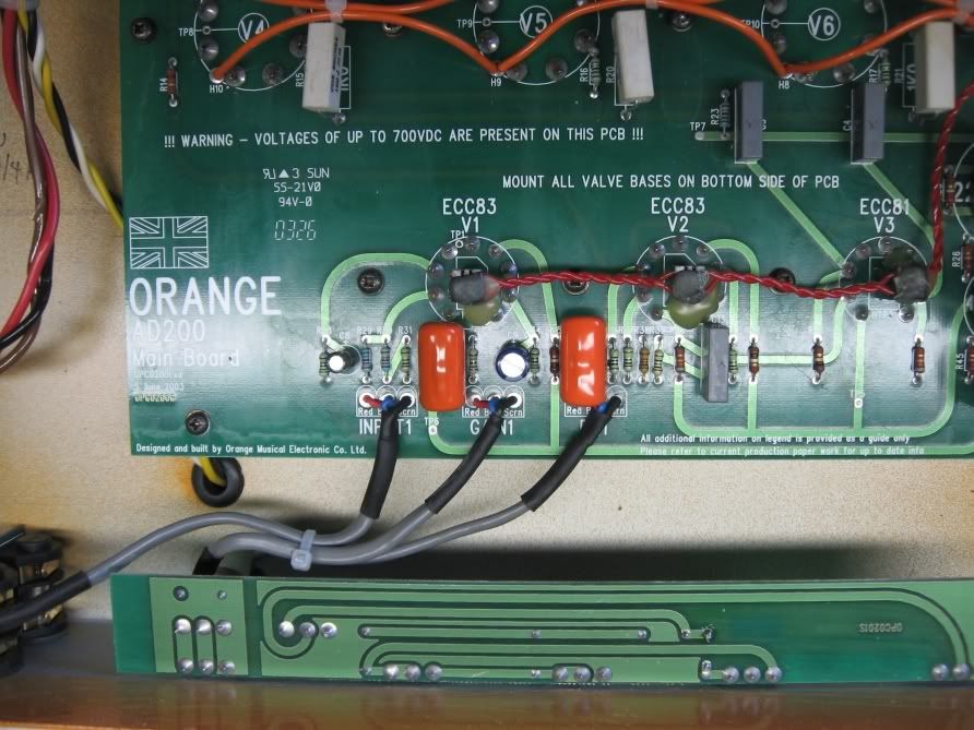
    Last edited by Alf; 05-24-2010, 08:18 AM.

  • #2

    Comment


    • #3
      Hiya. When you measure the 33v, where's your -ve lead?

      Getting solder out of plated-through boards is a nuisance. If it doesn't suck through the first time, try melting a bit of new solder on top and sucking again. If your iron isn't sitting in a tiny blob of solder it may not transfer enough heat through the hole to the stuff on the other side to melt it.

      Comment


      • #4
        Thanks , Alex for yor advice.

        I hadn't thought of sucking the solder. I left the board where it is , screwed down in the chassis.

        As I mentioned in my previous post there isn't any voltage on the pots.

        On V2 the first grid has 33 volt on it and the second grid has 22 volt.

        Does anyone know if the design could be based on an older orange amp ?
        So I can have look for reference.

        Alf

        Comment


        • #5
          Finally I found out by researching the internet . "Bernard d'Uur" a fellow forummember had a schematic posted somewhere.
          I take the liberty to refer to it here:
          I hope he doesn't mind.

          (Only 2 powertubes have been drawn , I think to make it more simple )

          http://i291.photobucket.com/albums/l...kIIIPreamp.jpg

          V2 is not the tonestack tube; it's already the PI and V3 (mislabelled V2 in the schem ) (ecc81=12at7) amplifies the signal further with more current I suppose !

          I have never seen this before in a guitaramp.

          So it's very logical to find voltage on the connection the 10K / 470 ohm and 2x 1M resistors.

          Alf
          Last edited by Alf; 05-24-2010, 02:24 PM.

          Comment


          • #6
            ...not sure the whole schemo is on the link - just one page is all I get. I'd be interested to see.

            As to sucking solder, yep just get your lips around the hole and inhale. Some people recommend using a straw but I think that's a bit gay.

            Comment


            • #7
              Here it is : Pi and poweramp

              http://i291.photobucket.com/albums/l...BMarkIIIPI.jpg

              Comment


              • #8
                Originally posted by Alf View Post
                V2 is not the tonestack tube; it's already the PI and V3 (mislabelled V2 in the schem ) (ecc81=12at7) amplifies the signal further with more current I suppose !

                I have never seen this before in a guitaramp.

                So it's very logical to find voltage on the connection the 10K / 470 ohm and 2x 1M resistors.

                Alf
                In this schematic, V1, V2, V3 and V4 are referring to the B+ voltages, not the tubes.

                Comment


                • #9
                  So , that explains ! Thanks.

                  Comment


                  • #10
                    Feel free to post the schematics!

                    Usually I use V's for tubes but I made it in a night and forgot to change the resdef.

                    V1 = preamp, V2 = PI (both 12AX7), V3 = buffer after PI

                    Comment

                    Working...
                    X