Ad Widget

Collapse

Announcement

Collapse
No announcement yet.

Sound City not enough negative voltage for biasing.

Collapse
X
 
  • Filter
  • Time
  • Show
Clear All
new posts

  • Sound City not enough negative voltage for biasing.

    Hello,

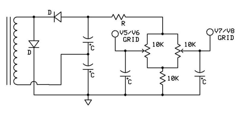
    I need some opinions on a biasing issue. I have a Sound City 120 that was converted over to DR103 specs. The negative voltage on the control grid is appx -37 with a 47k resistor/22k bias pot adjust in parallel with the 100uf bias cap going to ground. The power tubes are around 68ma WAY off the safe margin and the bias pot adjust seems to only adjust the negative voltage by -1v if that.

    Raising the bias resistor in 10k increments increases the negative voltage in very small steps. In order to get the ma per tube in mid to high 30's ma I have had to go up to a 2.7meg resistor. This just seems too high of a resistor value but it get's it into the safe ma draw range.

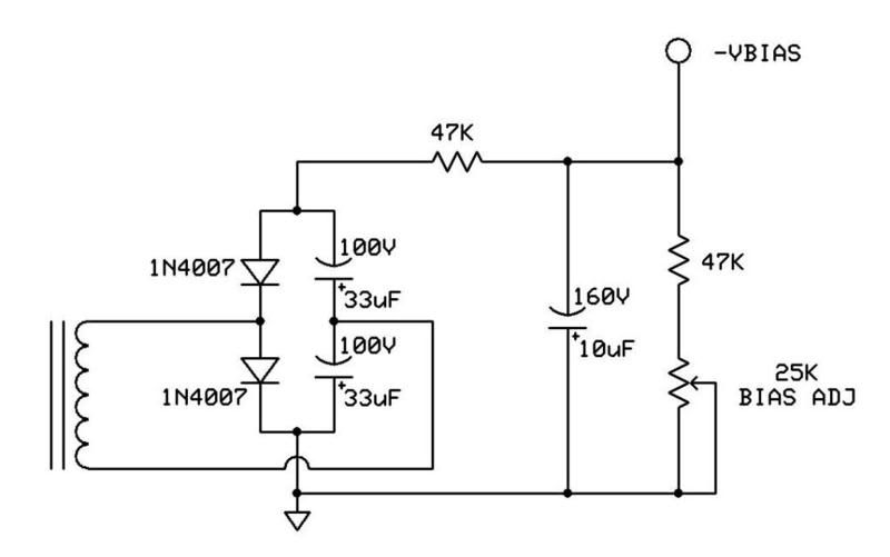
    The PT bias winding is appx 35v before it's rectified...it's really enemic. There is a 1k resistor after the bias diode. I would like to avoid buidling a voltage dubbler for the bias if possible. I could tie into the 350v sec on the PT taps to get more negative bias but would rather not do this if I can.

    Anyway's it just seems an awefully high resistor value to get this amp in a safe bias range. The old schematics call for a 47k, that's not going to work at all. Is using a 2.7 meg resistor to get the neg voltage in range a problem?

    Thanks for reading...

    Ampzone

  • #2
    It's a long time ago, but I converted the bias supply, on a 50 watt I had, to a voltage doubler. You'll never get enough bias voltage with a regular rectifier. Just be careful to get the caps the right way around!
    My band:- http://www.youtube.com/user/RedwingBand

    Comment


    • #3
      Thanks for the response. What do you think about the 2.7meg resistor getting the amp into a safe bias range? That is what concerns me having to go so high in value. Any thoughts?

      Ampzone

      Comment


      • #4
        So the bias supply has a 22k pot in series with a 2M7 resistor across it?
        If that works for now, fine, but when you come to change tubes it still may not be enough. Plus the pot can't be doing much.
        If you don't want a voltage doubler, at least try a full wave bridge rectifier on the bias winding, and reduce the 1k series resistor to 100 or 220 ohms. I can't see any other function for it other than to limit switch-on surge current.
        That may give you another 5V to play with.
        My band:- http://www.youtube.com/user/RedwingBand

        Comment


        • #5
          Ok the 22k pot was removed and now there is the 2M7 going accross the 100uf cap to ground. That get's it into a safe MA range for the tubes but what a high value! I am just worried that having 2M7 in there is a problem or I maybe it's fine. I'm just not sure. This is a set of Seimans El34's that will be staying for a while FYI.

          Yes there is 1k after the diode. I have never fully understood it's purpose?


          Now when you suggest a full wave bridge rectifier are suggesting to tie into the PT 350v taps and put a 110k 2w resistor in front of the bias diode like 50w DR504's had? If not please give me some more detail on this alternative.

          Thanks so much for the help here...I need it.

          Ampzone

          Comment


          • #6
            Originally posted by Ampzone View Post


            Now when you suggest a full wave bridge rectifier are suggesting to tie into the PT 350v taps and put a 110k 2w resistor in front of the bias diode like 50w DR504's had? If not please give me some more detail on this alternative.

            Thanks so much for the help here...I need it.

            Ampzone
            No, that's a "borrowed" bias supply and you can only do that on a full wave grounded center tap rectifier arrangement. You COULD do a capacitive divider arrangement like the JCM900s had with an HT circuit that uses a full wave bridge rectifier, but in this case it's not needed.

            I 2nd the doubler circuit. You would end up with more voltage than you know what to do with and will need to add a resistor upstream of your bias pots (probably something like a 15K or so). Something like this should suffice -

            Jon Wilder
            Wilder Amplification

            Originally posted by m-fine
            I don't know about you, but I find it a LOT easier to change a capacitor than to actually learn how to play well
            Originally posted by JoeM
            I doubt if any of my favorite players even own a soldering iron.

            Comment


            • #7
              The Voltage doubler is not a hard circuit to build and neither is taking the supply off of the plate. On the other hand the 2 meg resistor if it works is also fine. There is so little current in that supply to harm anything power wise or heat wise in reality.
              KB

              Comment


              • #8
                Originally posted by Amp Kat View Post
                The Voltage doubler is not a hard circuit to build and neither is taking the supply off of the plate. On the other hand the 2 meg resistor if it works is also fine. There is so little current in that supply to harm anything power wise or heat wise in reality.
                Lot's of great ideas here. I think I will stick with the 2meg if you guy's think that's not too off base.
                I know they take thebias supply off the sec PT 350v taps on the DR504. I will look at the schematic. I thought perhaps I could do this on this amp.

                Ampzone.

                Comment


                • #9
                  Originally posted by Ampzone View Post
                  Lot's of great ideas here. I think I will stick with the 2meg if you guy's think that's not too off base.
                  I know they take thebias supply off the sec PT 350v taps on the DR504. I will look at the schematic. I thought perhaps I could do this on this amp.

                  Ampzone.
                  If you look at the DR504 scheme, you'll notice that that circuit uses a full wave grounded center tap rectifier. On that topology a 1/2 wave rectifier off of one side of the HT winding works.

                  However, on this setup it's full wave bridge rectified. The only two ways to take a bias supply off of that winding would be to either use a 2nd FWB rectifier with two high value resistors (150K or so) upstream of it with the polarity reversed OR to use the capacitive divider method, which is a bit of a PITA in and of itself because you have to have a constant load on the HT supply at all times to keep it from hurting itself.

                  Since you have a bias winding already albeit at too low a voltage and the bias supply draws a natz ass of current, IMHO the 1/2 wave doubler I posted above would be the best alternative.
                  Jon Wilder
                  Wilder Amplification

                  Originally posted by m-fine
                  I don't know about you, but I find it a LOT easier to change a capacitor than to actually learn how to play well
                  Originally posted by JoeM
                  I doubt if any of my favorite players even own a soldering iron.

                  Comment


                  • #10
                    That diagram should be very helpful, Jon. I was trying to find something I could refer the OP to, but you schematic trumps anything I could find.
                    The 2M7 resistor is doing pretty much nothing, removing it would make no real difference to the circuit operation.
                    A resistor there is forming the bottom half of a potential divider on the bias supply, the top half being the supply impedance itself, in this case (most of which will be the 1k resistor).

                    'Now when you suggest a full wave bridge rectifier are suggesting to tie into the PT 350v taps and put a 110k 2w resistor in front of the bias diode like 50w DR504's had?'
                    No, I meant that you could remove the existing bias supply single diode/half wave rectifier (and the 0V connection from the other end of the bias winding), and replace it with a 4 diode full wave bridge rectifier, as per your B+ supply (except the +ve rectifier output would be the one connected to 0V, in the case of the bias supply).
                    This type of rectifier is a little more efficient, and in conjunction with reducing the 1k to 220R, would increase the available bias supply voltage.
                    My band:- http://www.youtube.com/user/RedwingBand

                    Comment


                    • #11
                      Thanks so much for the advice fellow...lot's to ponder on how I want to do with this. I may just stick with the 2meg in there now even though it makes me uncomfortable, even though there may be no reason to be concerned. That I had to go that high just gave me cause for pause.


                      Ampzone

                      Comment


                      • #12
                        Here's a scheme for a single point adjust voltage doubler bias supply I just built for a customer's Sound City amp -


                        With a 32VAC input voltage and the resistor values shown it should give you an adjustment range of -42V to -51V. Hope it helps.
                        Jon Wilder
                        Wilder Amplification

                        Originally posted by m-fine
                        I don't know about you, but I find it a LOT easier to change a capacitor than to actually learn how to play well
                        Originally posted by JoeM
                        I doubt if any of my favorite players even own a soldering iron.

                        Comment


                        • #13
                          I installed a voltage doubler in the L120 I used to have.
                          Webers book has a little section about adding the doubler circuit to Hiwatts (very similiar to SC) to obtain enough bias voltage,so they knew about this problem and fix a long time ago!

                          Comment


                          • #14
                            When I've gotten these in, they get either a full wave bridge or a doubler. If you took the 2M7 resistor out entirely, I bet you'd see little change in current draw of the power tubes.
                            -Erik
                            Euthymia Electronics
                            Alameda, CA USA
                            Sanborn Farallon Amplifier

                            Comment

                            gebze escort kurtköy escort maltepe escort
                            pendik escort
                            betticket istanbulbahis zbahis
                            deneme bonusu veren siteler deneme bonusu veren siteler
                            casinolevant levant casino
                            Working...
                            X