Ad Widget

Collapse

Announcement

Collapse
No announcement yet.

Problem with Boogie MkIIa

Collapse
X
 
  • Filter
  • Time
  • Show
Clear All
new posts

  • Problem with Boogie MkIIa

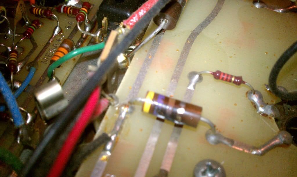
    I have a Boogie Mkiia which is i got back recently after it was with my sister in law for 15 years or so (stored in the garage i think). Whenever i try and turn on the lead channel (with foot switch or from panel) the relay starts going crazy and the sound gets really bad. I noticed that there are several broken solder joints and a resistor on tube socket is cracked (see picture)
    I have 4 groove tube power reducers with GTEL84S's in the amp (it does the same with the old tubes.)

    Could this be the cause of the problem or is it just an unrelated problem?

    Thanks

  • #2
    If I'm looking at everything correctly, that cracked resistor is a screen grid resistor on the power tubes, a 2w 470 ohm. I wouldn't think thats related, but needs repair!

    You say the relay goes crazy with either switch, so the switch probably isn't the fault, but the dc supply which feeds the relay, etc. It's the very bottom of this schematic:

    http://tubefreak.com/mk2.gif

    next to where is says "lead footswitch". From left to right, you'll see the fs jacks, the snubber cap and diode, the relay coil, the 68ohm resistor and finally, the cap and diode from the filament winding. (Super experts: is this like a villard rec or just a half wave drawn funny? If so how'd it get enough voltage? thanks!). Look over that area and post pics if you see oddness, test that 68 ohm resistor and if a visual inspection and checking parts while off doesn't yield any results / ideas.... Perhaps more pics of the "broken solder joints?"

    BE SAFE (I'm assuming here that you know what this means!!! LETHAL VOLTAGES INSIDE) and test the voltage at the relay (to gnd) with the lead switch on and off. See if there's ac on the circuit. If the relay's chattering, your on reading is probably bogus, but the total resting supply voltage is the first thing to worry about. You can do this while the amp is in standby, incidentally, not that it makes it much safer, and if you don't see what is on the scheme, keep moving back to the power supply until you do. I've heard of the relay failing in other mk2s, so if the supply is on the team, I'd think that's your suspect.

    Comment


    • #3
      The screen resistors are pretty obvious so change those but the relay "going crazy"......does that mean it chatters rapidly? If so, check the 470/16 filter cap and 1/2 wave rectifier diode that connects to the upper lead of the heater transformer winding. AC, or poorly filtered 1/2 wave rectified power to the relay would cause such chatter.

      Comment


      • #4
        That's exactly what it is doing. If it turn it on and pull the switch for the lead i can watch the relay chattering.

        BTW, thanks both of you for the quick response


        Originally posted by km6xz View Post
        The screen resistors are pretty obvious so change those but the relay "going crazy"......does that mean it chatters rapidly? If so, check the 470/16 filter cap and 1/2 wave rectifier diode that connects to the upper lead of the heater transformer winding. AC, or poorly filtered 1/2 wave rectified power to the relay would cause such chatter.

        Comment


        • #5
          Found more broken resistors

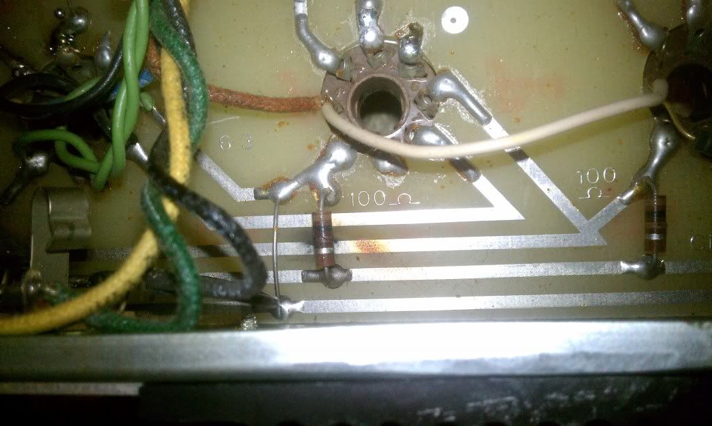
          I found 2 more broken 100 ohm resistors that go from the tubes to ground. (I think it is pin 2 on the tubes.) One has burn marks under it. How do i tell how many watts the resistor is?

          Thanks.

          Dan

          Comment


          • #6
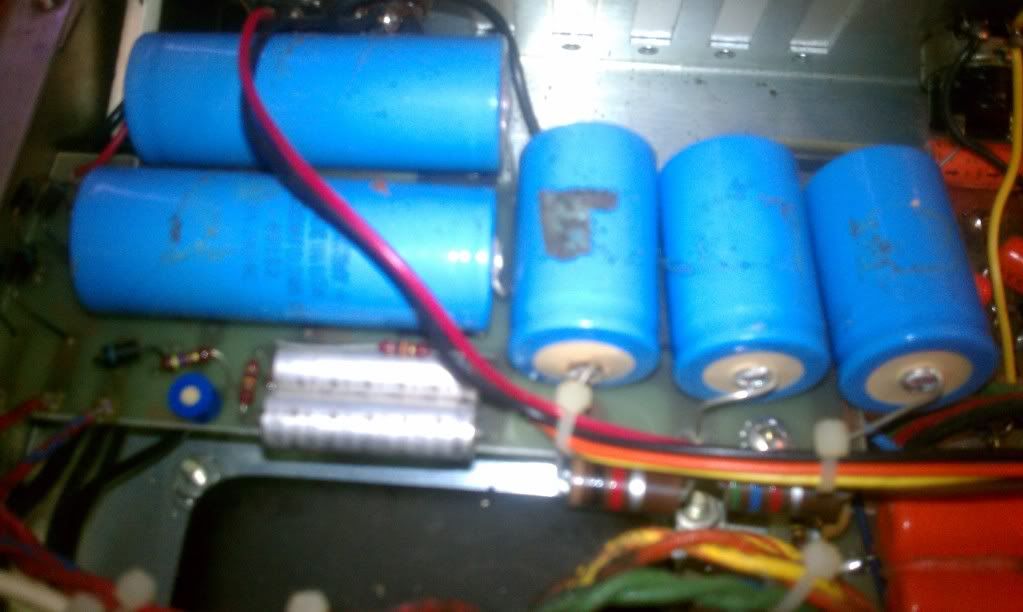
            I just keep finding more broken stuff At least one capacitors is bulging. Should i replace the others at the same time?

            Comment


            • #7
              don't get toooo far ahead of yourself, get the resistors on the team, if it's powering up now the cap will probably live through a few more power ups. There aren't too many 100 ohm resistors in that amp, so... post pics of those and any other things that are scaring you; Somebody can identify and confirm that part for you. The cap is dunzors and the rest may be crappy too, they're what, 30+ years old by now, so you may want to think about replacing those. The F+T (from watts etc, Watts Tube Audio ~ Everything Tube Amps!) are nice caps, with a compact body, you need to confirm the size as you have the thing in front of you, but iirc the original orange spragues are $!$. Fix the resistors while you're waiting for the caps, it probably won't catastrophically die, and if it does, it's an awesome show. Don't get it in your eyes.

              hey, HMHY and learn how the spot you're looking at in the amp corresponds to what youre asking about on the schematic, it's your best friend. "pin 2 on the tubes" could be a triode grid, or it could be a heater on a beam power tube or typical pentode. Since it's a 100R and it's "pin 2 on the tubes" I can guess its "center tap" of the heater string. Thats a potential big source of hum and possible instability on the same winding that powers the switching. If thats the case 1/2 watt resistors are just fine, as would be a 100 ohm pot, which would allow adjustable "hum dinging." Oh yah!
              Last edited by NorCalTuna; 03-28-2011, 05:16 AM. Reason: worse grammar than usual!

              Comment


              • #8
                The middle cap is the one that is bulging the most. The Top left one looks like it might have leaked something out (it's out of the picture i think.)


                Here are the resistors that have problems. They are both cracked and measure 8.3 and 9 ohms now.

                Comment


                • #9
                  wow.. thanks for the all the help guys I replaced the two broken 100 ohm resistors and that fixed it. The relay chattering is gone and the lead channel is working and quiet.

                  Comment


                  • #10
                    Hey, sweet! Did you get a new screen grid resistor on there? Replace them blue bulgin' caps dere and release the Rawk!

                    Comment


                    • #11
                      I replaced 4 resistors and also fixed the cracked solder, but it was the last 2 100 ohm resistors that fixed the problem. I still need to order the caps and fix a bad spot in the power cord where it comes in to the amp but it's working great now.

                      Comment

                      Working...
                      X