 Tweet
Tweet
Originally posted by 52 Bill
View Post
-
Is there something I can check with the multimeter that will tell me if the output tubes are ok? -
If cathode biased, getting roughly normal voltage on catodes is basically a clean bill of health.
For anything better you'd need a tube tester.Juan Manuel FaheyComment
-
Where would I find the correct voltages they should show?Originally posted by J M Fahey View PostComment
-
A copy of the original schematic could have that voltage listed.Originally posted by fastmerc View Post
What you need to do is to calculate the idle current draw of the two output tubes based upon the cathode resistor value and the voltages found in the output stage. Then compare the current draw with the published ratings for the tube type in the amp. That comparison would show you if the tubes are working in the range of normal values or if they are drawing too much or too little current.
Another thing to check is the bypass capacitor. They can develop problems from being to close to a hot cathode resistor, sometimes shorting out causing the tubes to get hotter than normal.
If you pull one of the two output tubes and read the voltage across the cathode resistor and then swap the output tubes and compare the draw of each tube to the other, that may give you an idea if one tube is drawing a lot more current that the other.Comment
-
I still can't find a schematic but have found they are EL90 tubes.Comment
-
The amp appears to have been made by Guyatone and as best I can tell their version of it is called a GA-520...still on the hunt for a schematic. I have mapped it out with pencil and paper but my sketch is no where near a schematic.Comment
-
I would change all the old caps (oil and alu electro). (Judging from the appearance of the parts) the amp (and the apparently stock components) are quite old (60s?). IME, the type of oil caps shown (the older ones--relatively newer (possibly starting from around the 80s but not completely sure) seem okay) are very likely to be bad (i.e. leaky) so I would just change them unless say, they are in a location with no DC on them. And doing some reading on basic theory would probably be helpful (how a tube basically works, how a power supply basically works, etc.) to get at least some idea of what you are looking at.Comment
-
Finding an actual schematic really isn't that important. Most of the parts are there and in place, so the details given on the schematic would be helpful, but not essential. A lot of schematic don't contain any voltage information.
There are a few (not many) amps that use EL90/6AQ5 outputs, try and find a schematic for one of them and compare the basic circuitry. There was a Gibson GA5 maybe and a lot of Japanese imports like Checkmates and Teiscos.Comment
-
I finally got in the new 1k Ohm resistor 5w resistor for the power supply section....but now when I switched on the amp it just blew the fuse. I replaced the fuse and it blew again. I removed the output tubes and tried one more fuse....blew again. So now I'm back to wondering what is up with it. It didn't blow fuses with the bad resistor still in place. I have since watched several video's to try and give me an idea of all the basic principles of how these work. This has no tube rectifier. So in going with that it is SS rectified I see 2 Diodes in series after the first resistor, but shouldn't it have 4 diodes to make a bridge rectifier?Comment
-
There would be 4 diodes if this circuit was full wave rectified, with 2 this is half wave rectified.Originally posted by fastmerc View Post
Are you certain that you replaced the 1K resistor correctly? What was wrong with the original 1K resistor? If it was open circuit, now you know why.
Look for a short in the power supply somewhere after the 1K resistor. Maybe a shorted filter cap or a shorted tube.
Now would be a good time to build a light bulb limiter.Comment
-
I'm pretty sure I replaced it correctly....I made sure to take a picture of how the old one was and connected the new one to the exact same tabs. The old resistor was open circuit. Any idea of the proper fuse I should be using just in case is the wrong type or rating? The fuse that was in there was a 250v Buss AGC 2 glass fuse. I will look into a lightbulb limiter.Originally posted by 52 Bill View PostComment
-
The 2 amp fuse should be more than enough for this amp.
It's hard to tell from your photos, but the 1K resistor seems to connect at one end to the diode string and the other end connects to the 20K resistor that is next to it on the tag board.
Discharge the filter caps and read the resistance from chassis ground to each of the terminals of the second filter cap. Any of them show zero ohms or near zero?Comment
-
Originally posted by 52 Bill View Post
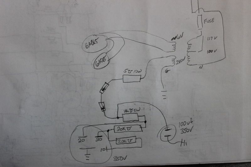
If Im doing it correctly, I don't get any ohms readings from any of the filter cap leads to ground. They all read open circuit. I am attaching a kindergarten attempt at a schematic for just this section.
Comment
-
I would try pulling the output tubes and firing up the amp (on a light bulb limiter, if you have one). See if the 1K resistor still bakes with the tubes removed."I took a photo of my ohm meter... It didn't help." Enzo 8/20/22Comment
-
I did try it without the tubes and it popped another fuse.Originally posted by The Dude View PostComment

Comment