Ad Widget

Collapse

Announcement

Collapse
No announcement yet.

Peavey 5150 t-former ??

Collapse
X
 
  • Filter
  • Time
  • Show
Clear All
new posts

  • #16
    Yeah. I just looked at the schematic and it does have that fuse.

    Rather surprising that they put a fuse on the 'secondary' of power transformer because most amps don't have it.

    That's good though, because it helps to protect the transformer.

    Comment


    • #17
      Why oh why did you start a second thread? Keep it all together and then we don't wind up responding to something in one that is already covered in another. DOn't make it harder to provide free assistance.

      Drilling out 8 little rivets is WAAAYYYY easier than unsoldering all those legs and then trying to get them back into holes.

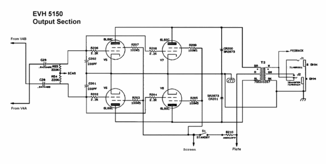
      By the way, that shematic looks nicer, but it is wrong. Screen and Plate connections have their labels reversed. Clearly the center tap of the OT primary should not be laveled screens and likewise the plates are not taken at the second filter.

      In this amp, the plates stay live all the time, and the B+ is broken to the screens and beyond.

      Let's get away from transformers, it seems clear yours are OK.

      If it holds the mains fuse with the standby off, then the OT is not shorted to something.

      Taking nothing from the above discussion, I offered some troubleshooting procedures inj your other thread, please try them too.

      If the amp hold fuses in standby, then the main rectifiers and filters are OK.

      I'd have to disagree with the loss of bias theory. if C41 shorts, the power tubes will run without bias. They will get red hot pretty quick, but that won't take the fuse out when the switch is flipped.

      With beer spills I worry most about arcs and remaining liquids.
      Education is what you're left with after you have forgotten what you have learned.

      Comment


      • #18
        Sorry enzo bout the new thread i just thought pretty soon no one would look at it.
        Ok i cleaned the board meaning power amp board and heres what happened i tested voltages w tubes out and every thing connected i had 193v on the 2a fuse in the rectifier circuit 192 on the one side of the 1st 2 diodes and like 12mv on the other side. with amp in standby. Then the next 2 diodes tested 182 on one side and like 12v on the other so i kept the tubes out and turned the standby on and everything held. So i decided to see what would happen with the tubes in and it blew the main 5a fuse and the 2a fuse in the rectifier circuit. so i replaced the fuse and disconnected the power amp tforme at the end of the board and every thing held.so i tested those leads on the t-former plug and the red was at 516v and hardly anything on the others. So i read ohms between all of the leads on the primary and got readings in the 20-30 ohm range. And i had continuity between the red and the blue and the red and the brown but not the brown and blue. the second time i powered it up after the 2a and 5a fuse blew i tried it again and just the 2a blew in the rectifier circuit. What do ya think? could one of the tubes be shorting out if it blew and causing this to happen?
        Last edited by spiderman2812; 04-02-2007, 10:46 PM. Reason: forgot something

        Comment


        • #19
          Originally posted by Enzo View Post
          Why oh why did you start a second thread? Keep it all together and then we don't wind up responding to something in one that is already covered in another. DOn't make it harder to provide free assistance.

          Drilling out 8 little rivets is WAAAYYYY easier than unsoldering all those legs and then trying to get them back into holes.
          By the way, that shematic looks nicer, but it is wrong. Screen and Plate connections have their labels reversed. Clearly the center tap of the OT primary should not be laveled screens and likewise the plates are not taken at the second filter.
          When I posted that schematic I thought something didn't seem right and didn't realize until afterwards that the plate and screen voltage labels were reversed.

          In this amp, the plates stay live all the time, and the B+ is broken to the screens and beyond.

          Let's get away from transformers, it seems clear yours are OK.

          If it holds the mains fuse with the standby off, then the OT is not shorted to something.

          Taking nothing from the above discussion, I offered some troubleshooting procedures in your other thread, please try them too.

          If the amp hold fuses in standby, then the main rectifiers and filters are OK.

          I'd have to disagree with the loss of bias theory. if C41 shorts, the power tubes will run without bias. They will get red hot pretty quick, but that won't take the fuse out when the switch is flipped.
          I was drawing on a problem I had with an old RCA PA amp that had a shorted bias cap that took out the rectifier tube. Mainly because someone had put an 8 amp fuse where a 2 amp fuse should have been.

          It didn't dawn on me at the time that the RCA was CATHODE biased and not fixed. You're right about it not blowing the fuses.

          I had mentioned earlier about checking the diodes CR200 and CR201 for shorts before proceeding, but I'm not sure if they got tested.


          With beer spills I worry most about arcs and remaining liquids.

          I agree. Cleaning would have been the first thing to do.

          BTW. Thanks for the help. Not being familiar with the 5150 makes it tough for me to recommend specific procedures as far as disassembly is concerned.

          That and the fact that I am not a full time tech and am only drawing on information from what I've had to repair in the past.

          Comment


          • #20
            Originally posted by spiderman2812 View Post
            Then the next 2 diodes tested 182 on one side and like 12v on the other so i kept the tubes out and turned the standby on and everything held. So i decided to see what would happen with the tubes in and it blew the main 5a fuse and the 2a fuse in the rectifier circuit.
            I agree with Enzo. I think the transformers, based on what you've said are fine.

            Did you test CR200 and CR201 to see if they were shorted?

            ------------------------------------
            Ok. I just looked at the schematic and realized that if the Plate voltage is always hot then the two diodes are probably fine. Otherwise the fuse would blow almost immediately when you turn on the power switch.

            But, I could be wrong, so I would test them anyway, just to be sure.

            I revised the schematic to show the Plate and Screen in the correct place.


            Last edited by Keystring; 04-03-2007, 12:29 AM. Reason: Schematic review

            Comment


            • #21
              yeah i tested them both and they tested 1.6 on the diode test setting on my meter. I assume thats fine because it said you would read nothing if it's bad . The only thing i'm concerned about is you said after that 2a fuse i should have like 485 volts on the diodes in the rectifier circuit and its only testing 192 fron diode to ground and i tested one of the resisstors on the + side of c34 and there was hardly anything there. Do you think that i should tear out the preamp board and start testing individual components in the rectifier circuit or do you think that maybe one of the tubes could be causing this? I know i probably need to pull c34 and see what happens. It almost seems like it's something in the power amp transformer but all of the components checked out on my multimeter unless those 2 diodes are blown but like i said they tested at 1.6v on the diode test.It's either the t-former or the tubes or something in that rectifier circuit. Those 1n4007 diodes read at about .6 on the diode test and that voltage seems awful low compared to 485 so could this happen if there was a blown tube in the socket? I feel like i'm loosing my mind!!!!!

              Comment


              • #22
                Originally posted by spiderman2812 View Post
                yeah i tested them both and they tested 1.6 on the diode test setting on my meter. I assume thats fine because it said you would read nothing if it's bad .
                Test them using the 'ohms' scale. Put the red probe on pin three of one of the power tube sockets and black one to ground. Adjust the scale on your meter until you get a reading.

                If you get a reading then reverse the probes and check them again.

                You should read nothing. If you get the same reading then it's probably blown.


                The only thing i'm concerned about is you said after that 2a fuse i should have like 485 volts on the diodes in the rectifier circuit and its only testing 192 from diode to ground and i tested one of the resistors on the + side of c34 and there was hardly anything there.
                You should be getting the reading on c34 which is on the other side of the rectifier circuit from the 2a fuse. Testing at pin 3 of the power tube socket should give you the same reading. Without the tubes in the reading will probably be higher.

                Do you think that i should tear out the preamp board and start testing individual components in the rectifier circuit or do you think that maybe one of the tubes could be causing this?
                No.

                Pull all the tubes and test the voltage again.


                I know i probably need to pull c34 and see what happens. It almost seems like it's something in the power amp transformer but all of the components checked out on my multimeter unless those 2 diodes are blown.

                but like i said they tested at 1.6v on the diode test.

                It's either the t-former or the tubes or something in that rectifier circuit.

                Those 1n4007 diodes read at about .6 on the diode test and that voltage seems awful low compared to 485 so could this happen if there was a blown tube in the socket?

                I feel like i'm loosing my mind!!!!!

                You don't need to pull c34. Just test the voltage either on the plus (+) side of c34 or check the voltage at pin 3 of one of the power tube sockets without the tubes installed.

                Since the Plate is always hot you can leave the standby switch off.

                Comment


                • #23
                  I could be wrong, but I get the impression you are not keeping the AC volts and DC volts organized. Measuring AC or DC either one from the fuse to ground will not be meaningful.

                  YOu got 500VDC without tubes. That means the transformer, the rectifiers, C34, and everything else that goes into making high voltage is OK.

                  If the fuses hold with no tubes, and the OT connector with the red blue and brown wires is CONNECTED in place, then those two diodes are OK.

                  Frankly, it sounds like you have a bad tube
                  Education is what you're left with after you have forgotten what you have learned.

                  Comment


                  • #24
                    Well i put the thing back together replaced the tubes and tada!!! It works. The only thing is the tube that wasn't working when i got it. well that socket doesn't seem to light up as in the heater. Is it possible the beer did something to the socket? It seems like the voltages checked out and i switched tubes around and for some reason they just don't glow in that socket. If you are looking at the back it's the 3rd one from the left?

                    Comment


                    • #25
                      Possibly loose pin on pin 2 or 7 in that socket. Pull the tube and look down the holes and see if that hole has the socket pin spread open mor than the others. Look at the solder under that sockets pins - you did unsolder them all and reinstall them didn't you? Make sure you didn't damage a copper trace and that the solder is good. The solder side should be facing you.
                      Education is what you're left with after you have forgotten what you have learned.

                      Comment


                      • #26
                        Thanks that was it. I appreciate all the help!!

                        Comment

                        Working...
                        X