Ad Widget

Collapse

Announcement

Collapse
No announcement yet.

I Messed up my Fender Stage 112SE

Collapse
X
 
  • Filter
  • Time
  • Show
Clear All
new posts

  • #16
    Originally posted by Enzo View Post
    It has been pointed out that you need insulating mica washers or equivalent. But what happened to the ones already in there? When you remove the transistors from the heat sink, the old mica washers generally either stick to the heatsink, or they come away with the transistor. They stick because of the tacky heat grease. Unless you destroyed them, they are usually reused.
    I haven't actually removed any of the transistors yet, just partially unsoldered them like 52 Bill and J M Fahey suggested. I'm assuming the mica's are still there. I was under the impression that I shouldn't re-use them (thought I read that somewhere). I will try to be careful during removal to not destroy them just in case.

    Hopefully my parts will be here by the end of next week so I can try and get this thing back together. Today, though, I will be building a light bulb limiter.
    Comment


    • #17
      If they are not damaged, use them again. If they crack in two or spall off some layers, then replace. I rarely have to get new ones.
      Education is what you're left with after you have forgotten what you have learned.

      Comment


      • #18
        Originally posted by Enzo View Post
        If they are not damaged, use them again. If they crack in two or spall off some layers, then replace. I rarely have to get new ones.
        OK, I'll try to save them if I can. If not, I will have a few spares.

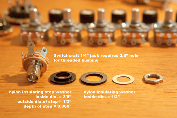
        Regarding the external speaker jack, how do the washers need to be oriented. I have 2 metal washers, and two nylon (or similar material) washers, one of them appears to have step on it, similar to this photo:

        Do the washers need to go on in the order shown here from left to right, with the chassis between the two nylon washers.

        For the transformer wires, there are 2 red, and 2 blue wires that run to the PCB. I want to make sure I do not have the two reds and the two blues backwards. I marked them before disassembly, but my marks rubbed off. Can these be installed backwards, or does in not matter? Is there a way find out which is which?

        Thanks again for all the help, looks like my parts will be here tomorrow.

        Comment


        • #19
          Correct about the jack washers, small end of step washer fits into chassis hole. For the wiring, the 2 reds are the same, the 2 blues are the same. It is AC and phasing doesn't matter here. When it matters the will put a stripe on one of each pair. If I misunderstood and you are asking if the reds and blues are interchangeable, definately not!
          Originally posted by Enzo
          I have a sign in my shop that says, "Never think up reasons not to check something."


          Comment


          • #20
            As g-one said, the two reds are interchangable, and the two blues are as well, but you cannot mix the red and blue.

            You have the schematic, it shows which pins get reds and blues.
            Education is what you're left with after you have forgotten what you have learned.

            Comment


            • #21
              Originally posted by g-one View Post
              Correct about the jack washers, small end of step washer fits into chassis hole. For the wiring, the 2 reds are the same, the 2 blues are the same. It is AC and phasing doesn't matter here. When it matters the will put a stripe on one of each pair. If I misunderstood and you are asking if the reds and blues are interchangeable, definately not!
              You understood correctly. I was worried I may have got the two red wires backwards. It was easier to tell from the photos I took which blue went where, but not the reds. That makes me feel better.


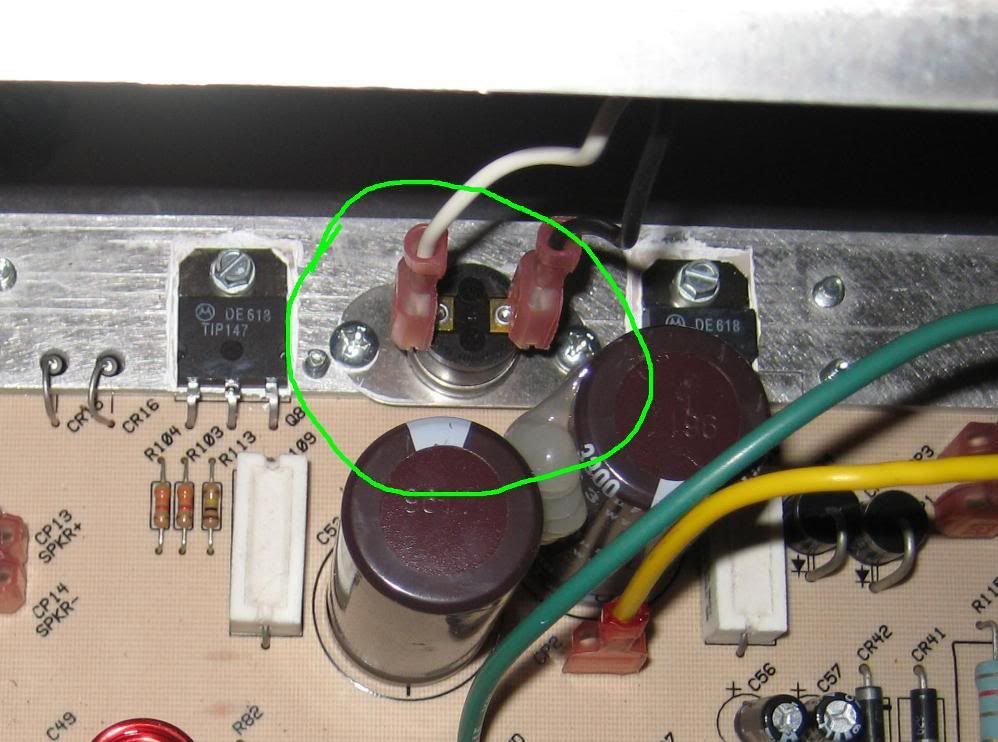
              Just out of curiosity, what is this component circled in green here? I've been trying to familiarize myself with all these components but couldn't find this on the schematic.

              Comment


              • #22
                That is a 195 degree F, normally closed, thermal switch.
                It is located at A-7 (lower left corner) of the schematic.
                It will open & turn off the mains (black wire)Vac in the event that the heat sink reaches the set point temperature.

                Comment


                • #23
                  OK, my Mouser finally showed up today (Thanks a lot USPS )so I didn't get a chance to swap out those transistors yet. I did go ahead and remove the old ones last night get the heat sink cleaned up. I was even able to salvage the mica insulators.

                  When I go to reinstall them, I put the thermal grease on both sides of the mica, right?

                  Another question about measuring resistors using my digital multi-meter. Some of the lower value resistors (.22Ω, 10Ω) read as 0 om my meter. A couple 47Ω resistors read as 23Ω. Does this mean they're bad, or does it mean my cheap multi-meter has trouble reading them?

                  Comment


                  • #24
                    I usually coat the back of the transistor, then stick the mica insulator to the silicon. Then I coat the clean side of the insulator and then mount the transistor to the heatsink.

                    The meter readings that you are getting can be partly due to a bad meter and also due to the interaction of the parts in the circuit. When you touch the two leads together what resistance reading do you get? If it reads 10 ohms you may need a new battery, or you may need to clean the test lead sockets. Or you may be in need of a better quality meter.

                    Comment


                    • #25
                      Very rare that a resistor goes DOWN in value, especially wirewound ones.

                      Please use part numbers. That 10 ohm resistor that measured zero, wouldn;t be R82 would it? Notice in parallel with it is an inductor. Inductors are coils of wire, and ones like this have extremely low DC resistance. That is why you get zero. Put a wire across any resistor and it will measure zero.

                      Got a couple 47 ohm ones that read 23 ohms? Would they be R75 and R76? Those two are in parallel. Two 47 ohm rsistors in parallel make about 23 ohms. And 0.22 ohm? ANY meter has trouble resolving those above zero.

                      You can never ignore the circuit around a part. As Bill said, interaction with other parts in the circuit can often skew readings
                      Education is what you're left with after you have forgotten what you have learned.

                      Comment


                      • #26
                        Originally posted by Enzo View Post
                        Very rare that a resistor goes DOWN in value, especially wirewound ones.

                        Please use part numbers. That 10 ohm resistor that measured zero, wouldn;t be R82 would it? Notice in parallel with it is an inductor. Inductors are coils of wire, and ones like this have extremely low DC resistance. That is why you get zero. Put a wire across any resistor and it will measure zero.

                        Got a couple 47 ohm ones that read 23 ohms? Would they be R75 and R76? Those two are in parallel. Two 47 ohm rsistors in parallel make about 23 ohms. And 0.22 ohm? ANY meter has trouble resolving those above zero.

                        You can never ignore the circuit around a part. As Bill said, interaction with other parts in the circuit can often skew readings
                        Yes to both. I have no idea about any of the theory behind any of this, so I didn't think to mention part numbers.

                        Anyways, I got my tip142 and tip147 installed, and everything hooked back up. Without the speaker wires connected, no instrument cable, and all pots on 0, I plugged it up to my light bulb limiter and flipped the switch. The bulb came on for a second at a low level, then after a second, dimmed even lower. I switched channels, and increased the pot values with no change in the bulb. I turned it off, then connected the speaker and turned it on again. Same thing, so I turned it back off, plugged up the guitar and turned it on again. No fuses blew, and the light bulb stayed dim.

                        Everything appears to be working good right now for the few minutes I played through it. I'll play through it some more tomorrow and see how it does.
                        Last edited by woodardhsd; 07-09-2011, 06:23 AM. Reason: Clean tone controls were on 0

                        Comment

                        Working...
                        X