Ad Widget

Collapse

Announcement

Collapse
No announcement yet.

3 lead Cap across vol ctrl on gibson skylark - what is its purpose?

Collapse
X
 
  • Filter
  • Time
  • Show
Clear All
new posts

  • 3 lead Cap across vol ctrl on gibson skylark - what is its purpose?

    Greetings all.

    I have a gibson skylark, 2x6EU7, 2x6AQ5 and a 6x4 rectifier. It's the model w/tremolo but no tone control.

    The schematic I have pretty much depicts the layout more or less, some of the coupling cap values are different, there is a 100n bypass cap on v1b-k and some other minor differences.

    One difference is the coupling to the vol control from the plate of v1a and the layout of the vol control.

    Click image for larger version

Name:	skylark_vol.jpg
Views:	1
Size:	42.0 KB
ID:	863759

    The coupling cap on the right is coming off the plate of v1a and is a .0047. I'm curious about the 3 lead cap across the vol control on the left.

    The schematic just shows a .022 coupling cap to the top of the vol control, the wiper going direct to the grid of v1b. The actual amp has the wiper going through a 100k resistor to the grid.

    I'm really looking for an explanation of the 3 wire cap across the vol control, and how the .0047 coupling cap and it work together... and any tonal ramifications of that configuration.

    EDIT: Here is the schematic that most closely resembles the amp:
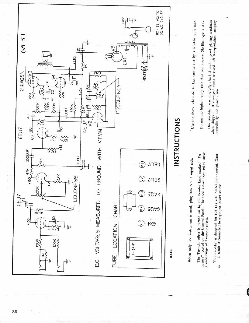


    Another interesting difference in mine vs. that schematic is mine has 100k plate resistors on both plates of v1 vs. the split 47k plate resistors on v1b on the schematic.

    And yes, it's been converted to a grounded plug and the .022 cap on the a/c line clipped out.

    Thanks,

    Wag
    Last edited by wagdog; 08-13-2011, 05:31 PM. Reason: added schematic link

  • #2
    I have no idea what the three terminal component you have is. I do know that Gibson used several custom multi component "modules" in their amps. There's a possibility that your particular amp is a tweener model that was a short run with an experimental part #. That part # being a pre packaged circuit. Some testing with a DMM and a careful drawing of the connections as they relate to the DMM readings could tell a story.
    "Take two placebos, works twice as well." Enzo

    "Now get off my lawn with your silicooties and boom-chucka speakers and computers masquerading as amplifiers" Justin Thomas

    "If you're not interested in opinions and the experience of others, why even start a thread?
    You can't just expect consent." Helmholtz

    Comment


    • #3
      It might be two caps in series.
      I can imagine one, say, .001uF or smaller in series with the volume pot (coupling) , and, say, 100pF across hot and wiper (bright) or some combination to that effect.
      It makes some logic if we consider that a smaller than original coupling capacitor would cut some bass, and the other one would add some treble, allowing some extra perceived headroom in a small amp, not bad.
      See that the *next* coupling stage has an impossibly small 250pF in series with 470K; more bass cut than what Vox used.
      We are talking around 1400Hz here.

      Tonal effect?
      1) lift the leg that goes to the wiper. Any change in brightness?
      2) connect the .0047 straight to the pot "hot", any increase in bass?
      3) I suspect best sound will be leave-it-as-is
      Please post your results.
      4) if you have a capacitance measuring function in your multimeter, use it on both halves.
      Anyway low values are more error prone.
      Juan Manuel Fahey

      Comment


      • #4
        From what I've found on those, it's an RC network with two caps and two resistors.

        http://www.paleoelectronics.com/2007/09/102c84/
        Last edited by icefloe01; 08-15-2011, 01:00 AM. Reason: grammar and make the url obvious

        Comment


        • #5
          Ahhh... The old "T" filter. Gibson used a few of those in various models, usually as a module component like this.
          "Take two placebos, works twice as well." Enzo

          "Now get off my lawn with your silicooties and boom-chucka speakers and computers masquerading as amplifiers" Justin Thomas

          "If you're not interested in opinions and the experience of others, why even start a thread?
          You can't just expect consent." Helmholtz

          Comment


          • #6
            Good to know, the classic Gibson mid cut.
            Juan Manuel Fahey

            Comment


            • #7
              Yep very primitive printed circuits. Sprague made a lot of them.

              Comment


              • #8
                Not a cap exactly...Sprague used to make these EQ modules for tube amps, it replaces several separate components. It's kind of like an antique integrated circuit.
                They made them for phonograph EQ too. Back in the day, lots of manufacturers used them.
                If you dig up a old Sprague catalog, it shows the whole circuit inside the module. It's resistors and caps in a compact package...used for Equalization, a preset tone curve.

                I gotta admit, as common as these were in the 1950s, they are impossible to find now. Used to see em everywhere. Erased from history.
                Last edited by soundguruman; 08-15-2011, 07:29 AM.

                Comment


                • #9
                  Originally posted by icefloe01 View Post
                  From what I've found on those, it's an RC network with two caps and two resistors.

                  102C84
                  Awesome find! The schematic on that site:

                  New Find : A Totally Different Crestline GA-5 Schematic


                  Closely matches my amp (.0047 coupling cap, grid stopper on v2a, .1 bypass cap on v2a cathode, and that integrated resistor/cap)! The only thing different is v2 on mine is another 6EU7, with one triode being used for the tremolo (which sounds great, btw).

                  Originally posted by soundguruman View Post
                  Not a cap exactly...Sprague used to make these EQ modules for tube amps, it replaces several separate components. It's kind of like an antique integrated circuit.
                  They made them for phonograph EQ too. Back in the day, lots of manufacturers used them.
                  If you dig up a old Sprague catalog, it shows the whole circuit inside the module. It's resistors and caps in a compact package...used for Equalization, a preset tone curve.

                  I gotta admit, as common as these were in the 1950s, they are impossible to find now. Used to see em everywhere. Erased from history.
                  I've seen some other skylark schematics with that same set of components, just didn't know they were in one package. That is cool. Some of the schematics I've seen have a .01 cap coupling cap followed by that network, with a .01 cap and 1M pot (one end grounded) between them:

                  Click image for larger version

Name:	skylark_tone.jpg
Views:	1
Size:	44.5 KB
ID:	821425

                  I'm actually tempted to mod mine like that as this amp is pretty bright and could stand a tone control. There are two inputs, so I could retask the input 2 hole for a tone knob. Don't really foresee plugging two guitars into it at one time.

                  Comment


                  • #10
                    Yes, it's actually an LCR network, in a compact package.
                    I ordered one from Gibson, and installed it in the 1970s, that was the first and only time. The one in the amp was broken off...
                    You of course can replace it w/ the standard stuff, like everybody else uses...no worries.

                    Comment


                    • #11
                      Originally posted by soundguruman View Post
                      Yes, it's actually an LCR network, in a compact package...
                      No, it's just an RC network as there aren't any inductors in the package.

                      Comment


                      • #12
                        Inductive resistors, it's an LCR network.

                        Comment


                        • #13
                          No inductors there, resistive or otherwise.
                          Juan Manuel Fahey

                          Comment


                          • #14
                            finished up the amp tonight...

                            I tried a few various configurations, bumping the first .0047 coupling cap to .01, adding a tone control between it and sprague cap/resistor made up of a .01uf and 1meg pot (seen in a lot of skylark amps). Didn't sound good, way to bassy (and not in a good way).

                            Just for grins, tried removing the sprauge cap/resistor combo and that really didn't sound good.

                            Ended up going back to the .0047 coupling cap, w/a .01 tone cap and 250k audio pot for the tone control - very nice.

                            Tried changing v1b's cathode resistor to a 1.5k bypassed with a 22uf cap (instead of the stock 2.2k and .1uf cap), and again way too bassy, woofy. Ended up with a 1.5k bypassed w/a .47uf cap.

                            The cathode cap on the two power tubes was old and leaking, changed it out w/a new 22uf cap.

                            Put in a weber sig series speaker a couple days ago.

                            Anyway, the amp sounds nice and tight now. The tone control works great, doesn't get too bassy, but can definitely get very bright.

                            These amps are pretty "thin" sounding, not anemic, but thin. They sound good loud, but not especially great fully cranked. There is a .002 cap across the plates on the power tubes - I was thinking of bumping that up to a .01 to see if it would get a little fuller sounding.

                            The output transformer is tiny - was thinking that a beefier unit might allow the amp to be pushed a little harder and not get splatty.

                            Comment


                            • #15
                              I agree... Any inductance properties those resistors have is probably so insignificant as to be ignored. Not that it "technically" isn't there, it just doesn't matter. I'm sure a glass specialist would tell you that most windows aren't technically clear too.
                              "Take two placebos, works twice as well." Enzo

                              "Now get off my lawn with your silicooties and boom-chucka speakers and computers masquerading as amplifiers" Justin Thomas

                              "If you're not interested in opinions and the experience of others, why even start a thread?
                              You can't just expect consent." Helmholtz

                              Comment

                              Working...
                              X