Ad Widget

Collapse

Announcement

Collapse
No announcement yet.

Laney vc30 -112 sound level problem

Collapse
X
 
  • Filter
  • Time
  • Show
Clear All
new posts

  • #16
    Agree and add: U3 might be dead (or very sick) or, as g-one states, might not be receiving its power rail voltages.
    Check that first and then whether you do not have DC on pins 1 and 7.
    Juan Manuel Fahey

    Comment


    • #17
      Hello,
      i tested D3 and D4, with multimeter in diode function, one direction they give 410 and 475, the other direction doesn't give anything. Does that tell me they are fine?
      Here the datasheet. I tested leg 1 vs leg 3, and the other way round. http://www.fairchildsemi.com/ds/BA/BAS16.pdf

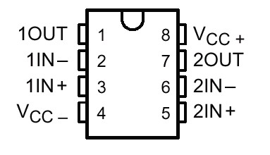
      About the ic U3: there is no indentation to tell me which pin is which, but after various trials I guess: pins 4 and 8 ( Ve+,Ve-) give a differential of 30v, and 15v tested against ground, so I suppose they get power. is that right?
      But I tested pins 1 and 7 and they don't give any voltage reading.
      As i was at that I tested also U1 and U2, and they behave the same apart pin 7 in U2 that gives -13v.

      Any ideas?

      Comment


      • #18
        The IC is TL072, a standard OpAmp with standr pin configuration:


        In a working bipolar supply circuit pin 4 should read the neagtive rail voltage, pin 8 the positive, and like you measured, the rail-to-rail voltage between pins 4 and 8 shold be 30V. So far this has been "correct".

        Rest of the pins whould, with no signal input, however read 0VDC. A 13VDC reading on the output you measured basically means the output is clamped to 13VDC constantly, which is the reason why little or no signal passes through to the following stage. This DC voltage in there could be due to leaky coupling cap between the stage and the PI or, even more likely, just a dead OpAmp.

        Comment


        • #19
          hi,
          so the damaged opamp would be the one that read 13v? that would be U2.

          They are tiny components, and I read they get damaged very easily; is it possible to change them with a simple solder?
          Also, what is that caused the damage? I could change it but maybe it would happen the same to the new one, if the cause is persistent.

          Thanks for your help

          Comment


          • #20
            Sorry, on a second glance, forget the earlier since according to your readings IC U3 seems to be in working order.

            I can't find the U2 but there are two U4's so I suppose the reverb signal recovery amp should really be U2 not U4. Is this correct?

            If so... Since the IC is a dual OpAmp one of its halves is simply disconnected. Schematic doesn't show how and which half and indeed improper termination of pins of the unused half could ilead to rail clamping. Since it (I reckon) is taking place in the unused section I think it shouldn't really explain the symptoms.

            If all the stages actually used in the circuit measure that 0VDC at inverting, non-inverting and output terminals everything should be fine on that regard.

            Comment


            • #21
              I hate to say this but your output transformer seems suspect. Hopefully, just saying that will make it untrue .
              Can you verify 40V at V3 cathodes. Also check the solder at P27 & P30.
              Originally posted by Enzo
              I have a sign in my shop that says, "Never think up reasons not to check something."


              Comment


              • #22
                V3 cathode(pin 8): 50V
                pin 27: 19V
                pin 30: 18V

                Comment


                • #23
                  Originally posted by g-one View Post
                  I hate to say this but your output transformer seems suspect. Hopefully, just saying that will make it untrue .
                  Can you verify 40V at V3 cathodes. Also check the solder at P27 & P30.
                  hello, what now?
                  10V difference at v3 cathode what does it show?
                  is 19v-18v at p307p27 normal?

                  Comment


                  • #24
                    The tub voltages seem close enough. Do you have a scope?
                    Also, just to make sure we have the right schematic, the year should be marked on the circuit board. What is it?
                    Originally posted by Enzo
                    I have a sign in my shop that says, "Never think up reasons not to check something."


                    Comment


                    • #25
                      Forgot to mention, U3 is still suspect. Easiest to just replace it. They are cheap. Rather than the indent shown in the datasheet, many have a round mark at pin 1 for orientation.
                      Originally posted by Enzo
                      I have a sign in my shop that says, "Never think up reasons not to check something."


                      Comment


                      • #26
                        Hello everybody.
                        g-one: It doesn't state the year, but having the 315mA HT fuse , I guess it has been built after '98.
                        I ordered the opamp, should arrive by Monday.
                        I don't have a scope

                        Losing hope

                        Cheers

                        Comment


                        • #27
                          Losing hope
                          C'mon bunzonoise, don't think that.
                          We've ALL been there many times (and probably will be again, sigh!)
                          That said, what's delaying this is that there are two different possible suspects, still not fully checked.
                          Their effect would be contradicting.
                          One is the Op Amp . Even both of them, to play it safe.
                          The other is the output transformer.
                          It might have shorted turns, in which case it would measure almost normal, yet suck your power output.
                          Just be patient and go step by step, there's no other (real) way.
                          The Hollywood version where the Hero/genius (played by Brad Pitt/Leonardo Di Caprio/Arnold Schwarzenegger or some other actor they *think* fits the role) just frowns (to show how determined he is), staring at the Infinite (to show how deeply thinking he is), maybe even sweats ot twitches (to show how strong an effort he's doing) and then smiles and screams "Eureka" or "I've got it" simply isn't true.
                          Oh well.
                          Start by replacing those Op Amps.
                          Desolder carefully, pamper the board.
                          Being a Laney I guess it must be half SMT, half through hole parts, isn't it?
                          Juan Manuel Fahey

                          Comment


                          • #28
                            ..waiting for opamps to arrive...

                            Comment


                            • #29
                              hi, I got the opamps, but in the meanwhile I was doing some more research and I found I could check opamps operativity connecting a powered speaker to the output pins, so I did it, and I got some signal, a distorted one though.
                              Then suddenly the leds went off and I smelled burnt somewhere. The tubes are still getting power, and from testing with the voltmeter, looks like nothing changed apart from the leds not working.

                              I still get the tiny distorted sound if I plug a cd player in the input and turn the volume all the way up, but I noticed that even switching to the clean channel, the volume pots that control this tiny sound are the ones in the drive channel.

                              The amp turns on even without HT fuse inserted, is that normal?

                              Any insight would be appreciated.

                              Comment


                              • #30
                                Originally posted by bunzonoise View Post
                                Hello everybody, I'm pretty new here.
                                but I can get only a faint sound(like headphones) from the amp, and only if I max the volume knobs. This happens in both clean and drive channels.
                                What your hearing here is actually your signal ringing through the tubes. This happens when you run the amp with no load (like with no speaker plugged in). I'm pretty sure it's really bad for the tubes, so I'd stop doing that, heh heh. Recently my friend brought me his Laney that was doing the same thing, and the problem in the end was a blown OT. He decided not to fix it though because he didn't want to spend the money on a replacement.

                                I would do some basic checks on the OT, and make sure that all of the OT connections are ship-shape.

                                Comment

                                Working...
                                X