i posted this on the unofficial acoustic amps forum but thought i would also post it here for those that aren't familiar with that site............
having had a few 3H inductors that were reading open on my 220 (two of them) and 320 (one of them) heads, a few weeks ago Russ Allee was both kind and generous to send me two of them for my 220 head from his parts bin. they worked perfectly and the amp is now up to spec. I got another 320 head about 2 weeks ago, and wouldn't you know it (?) one of it's 3H inductors on the graphic eq was also bad (the 70Hz one). so i contacted Russ, and unfortunately he was all out of these pieces of 'unobtanium', with no more on the horizon. on the 320 amp, instead of not working at all, it would work right after you turned the amp on, and continue to work fine until after playing it for about 5 minutes, then the 70hz slider had absolutely no effect. if you cycled the power off and then back on, it would work for a couple of minutes more, until again quickly fading into becoming unoperational. to make sure that it was just the inductor, i switched it with the 125hz one (also a 3H), and the problem followed the eq band (i.e. the 125Hz slider would work for 5 minutes and then stop working completely). i did a little research on the guitar forums, specifically about varitone circuits that use 3H inductors and found a thread about a guy that uses very small audio signal tranformers that are basically 3H inductors. he mentioned that the xicon #42TM018-RC was a 1:1 transformer that measured 3H on both sides, with a center tap on each side that measured 1.5H. i bought two of them (just to have a spare!) from Mouser for $2.47 each + shipping and they arrived today for testing.
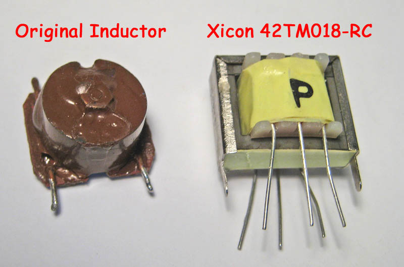
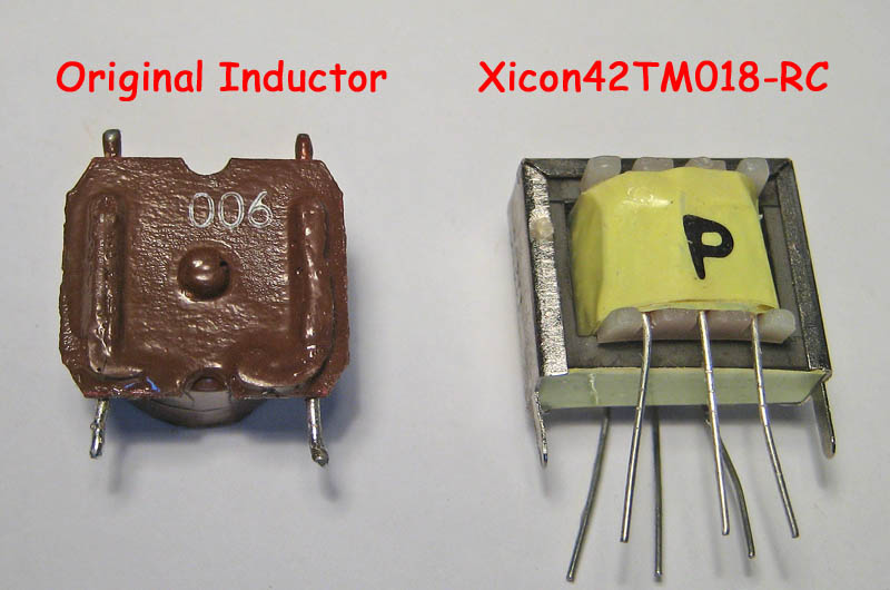
here's a couple of pics of the original one next to the Xicon transformer:


on one side of the transformer, it has a DCR of 601 ohms, and the other side measured 502 ohms, which is a bit higher DCR that the original one, so i decided to use the side with the lower DCR. Russ had warned me that since inductors are basically an antenna, that i should leave it's leads long, just in case i had to reposition it (possibly turn it 90 degrees) so that it wouldn't induce any hum. so the first way that i tried it was to just mount it standing up in a row with the original ones. i turned the amp on and voila! it works perfectly.
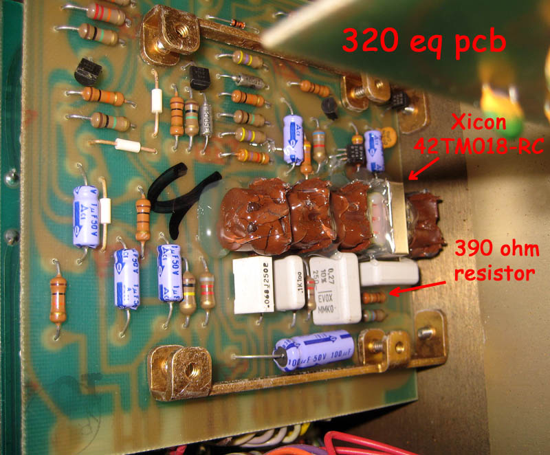
Note: on the 320 schematic, it doesn't have a couple of resistors that my amp (built the 45th week of 1979) has. on my amp there is a resistor feeding the inductors from the slide pot on the two low bands, whereas the schematic has none. feeding the 125Hz band, mine has a 390 ohm resistor and i noticed that with the new inductor the 125Hz seemed a bit less pronounced and a little higher in frequency than it was when the original one was working. the first thing that i tried was to shunt the resistor to make it like the schematic, and alothough the frequency and gain felt more like it used to be, at the very top of the slider's travel, it would make a slight clicking sound as you moved it. So, i added a 470 ohm 1/2 watt resistor on the bottom of the PCB in parallel with the 390 ohm one, giving it a total resistance of 213 ohms. i then tried it again and it works and sounds exactly like the original now with NO clicking whatsoever.
here's a pic of it mounted. i used hot glue to secure it to the other ones since these have been known to break loose after many years of use, and the new Xicon one has thin legs/leads that wouldn't support it very well.

note #2: these tranformers can induce hum, so thus far, i can only say that they'll work perfectly without adding any hum to a 320 head (and probably in a 220). i'm sure that they would work in a 370, however due to their different location of them in the amp, i don't know if they would cause any hum problems or not, but you could probably reorient it physically to work well with no issues.
having had a few 3H inductors that were reading open on my 220 (two of them) and 320 (one of them) heads, a few weeks ago Russ Allee was both kind and generous to send me two of them for my 220 head from his parts bin. they worked perfectly and the amp is now up to spec. I got another 320 head about 2 weeks ago, and wouldn't you know it (?) one of it's 3H inductors on the graphic eq was also bad (the 70Hz one). so i contacted Russ, and unfortunately he was all out of these pieces of 'unobtanium', with no more on the horizon. on the 320 amp, instead of not working at all, it would work right after you turned the amp on, and continue to work fine until after playing it for about 5 minutes, then the 70hz slider had absolutely no effect. if you cycled the power off and then back on, it would work for a couple of minutes more, until again quickly fading into becoming unoperational. to make sure that it was just the inductor, i switched it with the 125hz one (also a 3H), and the problem followed the eq band (i.e. the 125Hz slider would work for 5 minutes and then stop working completely). i did a little research on the guitar forums, specifically about varitone circuits that use 3H inductors and found a thread about a guy that uses very small audio signal tranformers that are basically 3H inductors. he mentioned that the xicon #42TM018-RC was a 1:1 transformer that measured 3H on both sides, with a center tap on each side that measured 1.5H. i bought two of them (just to have a spare!) from Mouser for $2.47 each + shipping and they arrived today for testing.
here's a couple of pics of the original one next to the Xicon transformer:


on one side of the transformer, it has a DCR of 601 ohms, and the other side measured 502 ohms, which is a bit higher DCR that the original one, so i decided to use the side with the lower DCR. Russ had warned me that since inductors are basically an antenna, that i should leave it's leads long, just in case i had to reposition it (possibly turn it 90 degrees) so that it wouldn't induce any hum. so the first way that i tried it was to just mount it standing up in a row with the original ones. i turned the amp on and voila! it works perfectly.
Note: on the 320 schematic, it doesn't have a couple of resistors that my amp (built the 45th week of 1979) has. on my amp there is a resistor feeding the inductors from the slide pot on the two low bands, whereas the schematic has none. feeding the 125Hz band, mine has a 390 ohm resistor and i noticed that with the new inductor the 125Hz seemed a bit less pronounced and a little higher in frequency than it was when the original one was working. the first thing that i tried was to shunt the resistor to make it like the schematic, and alothough the frequency and gain felt more like it used to be, at the very top of the slider's travel, it would make a slight clicking sound as you moved it. So, i added a 470 ohm 1/2 watt resistor on the bottom of the PCB in parallel with the 390 ohm one, giving it a total resistance of 213 ohms. i then tried it again and it works and sounds exactly like the original now with NO clicking whatsoever.
here's a pic of it mounted. i used hot glue to secure it to the other ones since these have been known to break loose after many years of use, and the new Xicon one has thin legs/leads that wouldn't support it very well.

note #2: these tranformers can induce hum, so thus far, i can only say that they'll work perfectly without adding any hum to a 320 head (and probably in a 220). i'm sure that they would work in a 370, however due to their different location of them in the amp, i don't know if they would cause any hum problems or not, but you could probably reorient it physically to work well with no issues.

Comment