Announcement

Collapse
No announcement yet.

Peavey Valveking VK212 issue

Collapse
X
 
  • Filter
  • Time
  • Show
Clear All
new posts

  • Peavey Valveking VK212 issue

    I've got a Peavey Valve King combo here in the shop that has me puzzled. It came in completely dead and inspection revealed a shorted power tube and a blown filament fuse on the board. Further checking showed that two of the diodes in the filament bridge supply were bad. I changed out all four filament diodes and was rewarded with filament voltage and a pilot light. Great, I thought, this thing will go away and leave me happy. No such luck.

    the channel switching didn't and doesn't work. On one side of R212 I have about 30v, but on the other side what's supposed to be 14v (enough to energize the switching relays) is only about 3v. At rest the 5w 400 ohm resistor measures about 250 ohms.

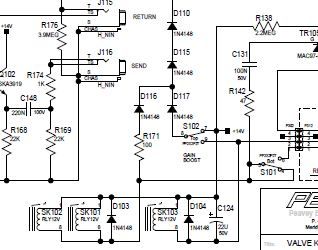
    I'm suspicious of C216. I replaced D103 and D104 on the theory that what damaged the rest of the diodes might have done a job on these but it didn't fix the problem.

    Any thoughts as to what could be dragging the voltage down? Any and all suggestions gratefully accepted.

    I've included a clip of the filament supply


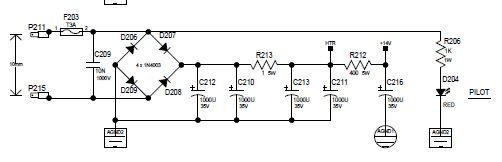
    and where the 14v is supposed to go


  • #2
    Perhaps you are looking TOO closely.

    The relays run on the 14v supply, but that is not the only place 14v goes. The reverb IC runs on 14v. Is it getting hot? Or is it cracked? A shorted IC would load down your 14v. That would be my first suspect.
    Education is what you're left with after you have forgotten what you have learned.

    Comment


    • #3
      I had to put this aside for a couple weeks while I worked on other stuff around here. I saw where you helped another fellow out with a similar or the same problem on another Valvekingand he ended up solving it because Q103 had died. With the number of power tube failures we're getting these days this has got to be a fairly common problem.

      The filament circuit took a helluva jolt when the one power tube shorted out, if it blew the fuse and two of the diodes in the bridge. It looks like I did replace the reverb IC and even installed a nice socket for it and changed Q102 at the same time. I do not have the foot switch for this amp if that's significant, I'm using the push buttons on the panel.

      Ah well back to the drawing board and at my age too, heh heh. I shall know more after I pull the board out again. I hate working on live boards.

      Comment


      • #4
        If the reverb IC is socketed, then no problem just removing it for now. Isn;t in backwards is it?

        As I suggested elsewhere, follow the 14v rail from its source at the 5w resistor. Look along all the traces for possible solder bridges or bad ribbon cables.
        Education is what you're left with after you have forgotten what you have learned.

        Comment


        • #5
          I've got it fixed.

          After rechecking my work with inconclusive results, I used a smallish battery eliminator left over from my radio days to give me twelve volts on a couple of probes. Two of the relays gave a healthy clunk when the coil was powered but SK103 only let out sort of a wimpy *tink*.

          Believe it or not the hardest part was coming up with an equivalent part number for this signal switching relay. Although Sun Hold relays are not generally available here I was able to obtain a data sheet for the relay in question which gave me important information such as the pinout, the hold and release voltages, the coil resistance and the footprint. Once I had that I dug through the Mouser hard copy catalog until I found an equivalent to the Sun Hold TDS 1202L relay-it is Mouser part number 655-V23105A5303A201 made by Axicom and it costs about two dollars-they have plenty of them too. At the same time I changed the two JFET switches that are involved with this circuit on general principles.

          Once you've got something working the perspective on why it quit is a lot clearer. This relay is latched as soon as you power the amp up. I figure that when the power tube shorted out, the surge took everything out before the fuse had time to react. It took out the diode bridge, cooked the relay, and maybe the diodes paralleling the relay coils.

          UPDATE: Seems like I spoke too soon. I plugged the reverb tank in and gave it a tap-it let out a satisfying pong but is not passing signal so something's amiss on the input side of the equation. Back to work.....

          UPDATE 2: Diode D118 had been fried in the general meltdown. I've got a working amp if the effect loop is OK.
          Last edited by Prairie Dawg; 04-13-2012, 06:11 PM.

          Comment

          Working...
          X