Ad Widget

Collapse

Announcement

Collapse
No announcement yet.

Cap can question

Collapse
X
 
  • Filter
  • Time
  • Show
Clear All
new posts

  • Cap can question

    Hello!!

    Finally i open the cap can in my Pro-reverb clon (Guyatone GA-1050) and found this....
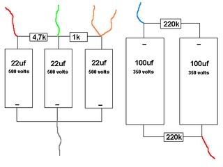


    I would like to know if it is in Blackface specs... Pre-owner change some Silverface values (P.I., tone stack...) but i think all is original in the filters caps...

    best regards from Spain!!!
    Last edited by chocopower; 05-31-2007, 10:19 AM.

  • #2
    Resistor & cap vallues are near enough, Fender used 1K in place of the 1.7K that you have but I don't think that 700ohms is going to make or break the amp.

    One query - your diagram shows the 100uf caps as being in parallel/aligned in the same polarity ("+" to "+")? Now if there is a jumper wire running diagonally from one cap's "+" to the other cap's "-" (but not the terminals that connect to B+ or ground) then everything is OK. Check continuity from the junctions of the 100ufs & 220Ks from bottom left to top right on your diagram, you should have 0ohms.

    Comment


    • #3
      upsss.... you are on right.... the 1,7k resistor is a "bug"... it is really a 1k.

      Weeks ago you help me whith this mod:

      http://music-electronics-forum.com/s...ead.php?t=2713

      could you explain it, (again), in my cap can lyout? (just for dumb techs... )


      This week iŽll chek the cap polarity.... It,s is really strange....

      best regards from spain!!!!!

      Comment


      • #4
        Replace the 1K with a 4.7K 3W. Replace the original 4.7K with a value that will result in 220-230v on the 12AX7 plates in V1...I'd guess at 27K for a starting point.

        With a 12AX7 phase inverter this will give you more of a pre-blackface vibe. If you need to restore the BF style "chime" to the reverb channel replace the cathode cap & resistor at V2, pin 3 with 2.7K/15uf or 3.3K/10uf (depending on how easy it is for you to find a 15uf cap).

        100uf filters - There's no reason why the caps can't be fitted with "+" to "+" AS LONG AS THERE IS THE JUMPER that I mentioned (missing from your diagram but should be in the actual amp). Fender arranged them in a more logical sequence but schematically they are the same thing. I often fit series filter caps the way that they are shown in your diagram, if there are restrictions in the amount of space/eyelets that you have to play with.

        Comment


        • #5
          Originally posted by MWJB View Post
          ...Replace the original 4.7K with a value that will result in 220-230v on the 12AX7 plates in V1...I'd guess at 27K for a starting point....

          How should i check this voltage?
          Pin 1 and Pin 6 to ground?

          Comment


          • #6
            That's right, if you end up with a little less than 220v I wouldn't panic. If you get much less than 200v (I doubt that you will as preamps draw very little current and you need a big jump in resistor value to get a significant change) have a listen first then decide if you want to go up in voltage. Likewise if you get up to 240v, that's still ball park.

            Comment


            • #7
              more questions about this mod in the right post....

              http://music-electronics-forum.com/s...ead.php?t=2713

              Comment

              Working...
              X