https://dl.dropboxusercontent.com/u/...0schematic.pdf
Here is a copy of the schematics.
It first started as an intermittent problem but has progressed into a constant. It fires up and works great for like 3-5 mins but then suddenly all output stops except for a loud hum/buzz that isn't affected by the volume control. You can switch off the standby switch to stop it from coming out the speakers but if you turn it back on its still there. If I power it off completely for about a min its good to go again for the couple of mins. All tubes are good as I've swaped them all out individually and have extra's that are known good as they work fine in my Fender bandmaster.
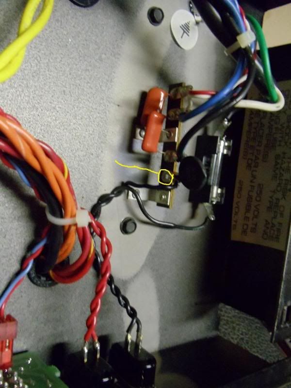
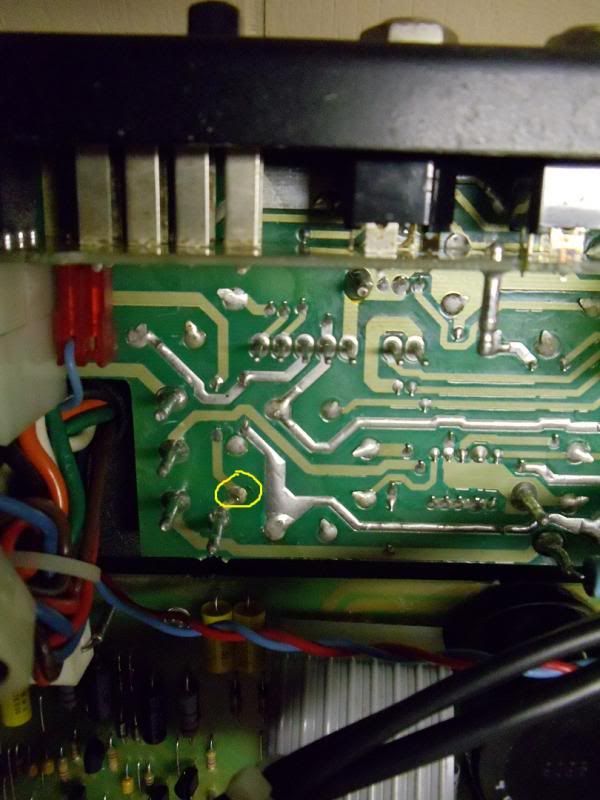
I found a couple small things when I ripped it apart. There was one broken solder joint on 1 of the pins of one of the power tubes and also a broken solder joint on ceramic disk right after the power switch. I'll look at the schematics to refer to what they are exactly in a min.
Other than that I reflowed all the solder joints. Visually inspected the caps for leaking/bulging. Cleaned all the pots. Retensioned the power tube socket pins. Cleaned and looked for any visual damage of all the ribbon cables and other internal connections.
I'm not all that knowledgeable when it comes to electronic circuits and components but some basics and can't really follow a schematic without getting lost or understanding why each component is there and why. If you guys have anything for me to test I can try. Just have a basic multimeter.
Edit - ok it looks like the first component that had a bad solder joint is on the last page of the schematics on the power chord circuit. The black of the chord runs into the main fuse then to the power switch and from there to the component which seems to be labeled cl60 on there. From this component the wire runs to the black wire into the power transformer and 1 pin of the ground lift switch.
I'm not sure which pin it was on the power tube as I don't know which way to count the pins. If I go from the key hole in the socket do I go clockwise or counter clockwise from it. If I'm looking down into the socket where the tube goes in from the back panel of the amp it would be 1 pin counter clockwise from the key hole. The key hole is facing left towards the output tranny. It appears that that pin isn't even used on the actual tube.


Comment