 Tweet
Tweet
Originally posted by g-one
View Post
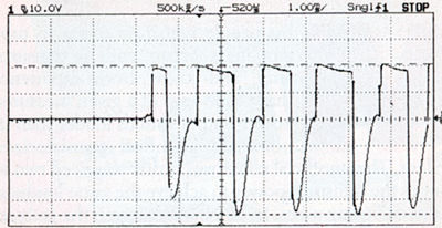
But you're saying that once the waveform starts clipping at the top and bottom then all-bets-are-off anyways for getting that crossover point to not look terrible? My concern was initially that the amp sounded "buzzy" when cranked to distortion and I thought that the crossover spikes might be causing that harshness and maybe that was because of a problem with the amp itself.

Comment