Announcement

Collapse
No announcement yet.

Question for those who have stared at a scope screen for decades

Collapse
X
 
  • Filter
  • Time
  • Show
Clear All
new posts

  • Question for those who have stared at a scope screen for decades


    Actually two questions.

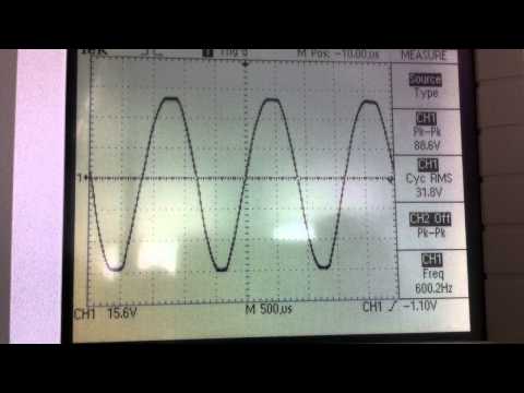
    Why does this scope image jitter up and down at the peaks?? Does it signal some sort of distortion or possibly a power supply problem where the caps for B+ or screen voltage are struggling? I ask because the amp on scope is a Sound City 120 which has been recapped, except for the two big 200uF/350V power supply caps. I have to order them, but the rest I had on hand.

    Is there a place online (or a book) for reference that shows visuals of different types of distortion or instability on a scope screen and tells what they mean, or what to look for "if you see this" type of thing?

  • #2
    Originally posted by nsubulysses View Post
    ...Why does this scope image jitter up and down at the peaks?...
    A couple of comments:
    I do not believe that the signal, as shown in the YouTube video, is entirely real. There is some kind of artifact effect caused by that model of scope or the video recorder. I'd guess that the signal is showing the effects of ripple at high amp power levels or there could be some parasitic oscillation at the peaks and valleys of the signal. Can't tell for sure from that vid. Does the effect stop when you reduce the signal a little? If so I'd say it's the 120Hz ripple that commonly occurs when high current is drawn by the power amp. If the effect only happens when the amp is putting out near full power then I's say that the amp is performing within it's design capabilities. If it does that at lower (90% of full power or less) then I'd say there is a problem with the amp.

    Originally posted by nsubulysses View Post
    ...Is there a place online (or a book) for reference that shows visuals of different types of distortion or instability on a scope screen and tells what they mean, or what to look for "if you see this" type of thing?
    Scope photos were pretty common in the old, non guitar amp books. I think you can find that stuff at the PMillett book scan site. http://www.pmillett.com/technical_books_online.htm.

    By the way, in the trade, "jitter" when applied to a scope trace description means time axis variations.
    Last edited by Tom Phillips; 09-30-2014, 11:53 PM. Reason: Added link

    Comment


    • #3
      Agree with Tom that it is probably ripple. You will usually see some modulating the signal a bit when you hit clipping with the power amp. If you slow the trace down and sync to line you should be able to see the ripple waveform riding on the signal.
      Originally posted by Enzo
      I have a sign in my shop that says, "Never think up reasons not to check something."


      Comment


      • #4
        Would this be what your looking for?

        Thanks,
        nosaj
        Oscilloscope Testing of the Audio Amplifier.
        Understanding Audio Distortion
        soldering stuff that's broken, breaking stuff that works, Yeah!

        Comment


        • #5
          Digital scope, not showing real time trace. I'd agree that is probably power supply ripple. A little of which will always be present on the first B+ reservoir cap. Slow the sweep down so a lot more cycles of the signal wave appear on screen. You probably would then see the tips of the wave are no longer even at the top. If you upped the test freq to 1200Hz, then you should see the tips on the scope as having a pattern of change that was 10 cycles long. IN other words the first peak on the left would be full voltage, then each next peak going to the right would be slightly lower until we got to the tenth which would be the lowest yet. Probably easier to see on AC coupling and zoomed in on the peaks.


          As you slow the sweep down, as the trace looks less like a waveform but more like a solid pattern, the top and bottom edges of the trace pattern ought to take on the shape of the ripple pattern.
          Education is what you're left with after you have forgotten what you have learned.

          Comment


          • #6
            I think I see what you mean. It does seem to only happen when the amp is at clipping, putting out full power.

            Here is a close up of the ripple

            Comment


            • #7
              And slowing down the time base as was said. I think this is the ripple you mean?


              It seems this ripple is excessive. I cannot quantify this in any way, but I just say this because it stuck out to me compared to viewing other amps. If it can be said from my little youtube clips, does it seem like a lot of ripple or normal? As I said before it has original 200uF/350V caps which need to be replaced. They test over 200uF capacitance but they are visibly leaking a bit, so I'm sure that's not helpin

              Comment


              • #8
                It looks normal to me.
                Tom

                Comment


                • #9
                  yes clearly a ripple pattern. Your digital scope wants to put up an average picture of a more or less repetitive waveform. So looking at the newer pictures, see how the overall sine wave has the ripple superposed on it - or is it the other way around, hmmm? - So some of the peaks are full size and some are lopped off, The changing display you started with is the result, sometimes the scope latches on one, and sometimes the other. So it snaps from shape to shape at the tips.

                  By slowing it down, we see the larger picture of the signal wave being modulated by the ripple.


                  Too much? Hard to say. If you have 400v of DC, a couple volts of ripple is to be expected. 20v of it is not. So pick a sweep that lets you conveniently see the amount of ripple, and decide how muchy yo0u HAVE, then decide if it is too much. If you can;t hear it, I'd be inclined to think it was not "too much."
                  Education is what you're left with after you have forgotten what you have learned.

                  Comment


                  • #10
                    This is great info thank you all for your replies. I am a little confused on how exactly to measure the ripple. Is either of these ways correct?? Hope this isn't an excessive amount of videos but it really helps me show what I'm seeing and I think it helps you knowledgable people steer me right too.

                    .5V/divsion with ripple centered, seems to show rippling for about half a division. Meaning I have about a .5V pk-pk ripple?

                    Comment


                    • #11
                      Or scope zoomed in on single waveform, trying to center the ripple. Again .5V/div. Seems to show maybe 1.5V pk-pk ripple??

                      Comment


                      • #12
                        double post whoops

                        Comment


                        • #13
                          Originally posted by nosaj View Post
                          Would this be what your looking for?

                          Thanks,
                          nosaj
                          Oscilloscope Testing of the Audio Amplifier.
                          Understanding Audio Distortion
                          I have yet to read through these but have given them a quick look and YES this is the type of thing I hoped to find. Thank you! I have seen some of those shapes before and wondered what they signaled.
                          Last edited by nsubulysses; 10-01-2014, 04:27 AM.

                          Comment


                          • #14
                            Your video's really help to clarify what's going on. Trying to describe what you are seeing with a narrative would be painful and confusing.

                            The analog scope gives a better presentation in this situation. Try setting your trigger source switch to "LINE." That should stabilize the display with respect to the ripple. From your description I think you are interpreting the ripple correctly and it still seems to be within the norm to me. Does the ripple diminish greatly if you back off on the drive amplitude to the power amp a little? That would also be a normal response.

                            You originally said that the Sound City 120 has been recapped, except for the two 200uF/350V power supply caps. You did not say how old those caps are. It is possible that replacing those, if they are more than 10 years old, will improve the ripple but that is not guaranteed. Even new amps often exhibit the ripple.

                            As you use the scope to observe the waveform on additional amps you will gain the experience to know what is normal and which waveforms indicate abnormality. It is also good experience to sample the waveforms in various stages of those amps that have no issues so you know what is normal.

                            Nice to have a 465B scope!

                            Cheers,
                            Tom

                            Comment


                            • #15
                              What freq are the signals in question? Usually when I see low frequency riding on the audio it's multiples of the line frequency- in my case usually it's 120hz from full wave rectified AC.

                              In a push-pull amp it doesn't matter so much as the ripple cancels itself out of the audio at the power amp. By the time power gets filtered down past the screens and phase inverter that stuff is usually so far down it's north worth worrying about.

                              Jamie

                              Comment

                              Working...
                              X