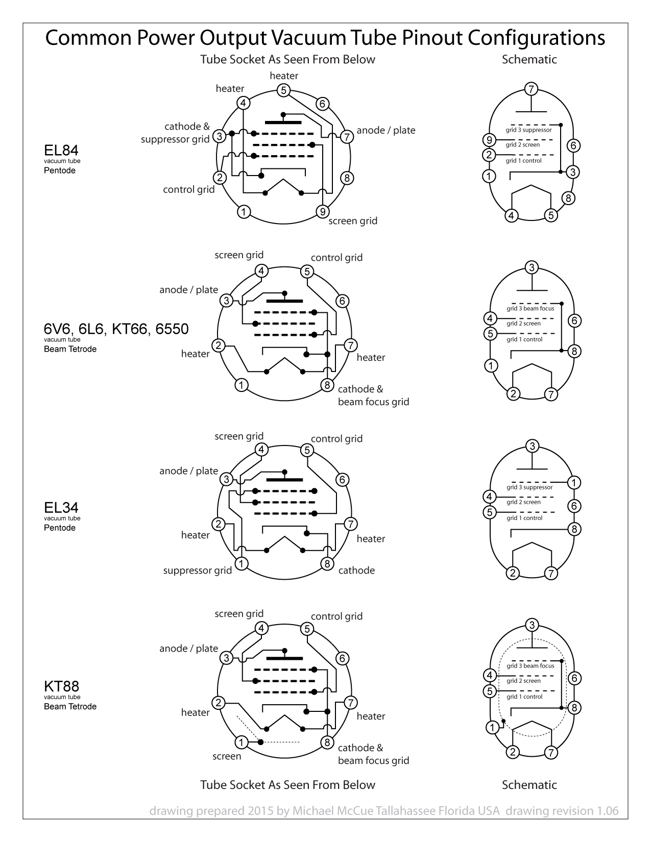
Tube socket wiring diagram:
Some of my guitar playing acquaintances were discussing swapping tube types in amps and I wanted to point out some of the differences in socket wiring that one should consider before swapping tube types. I know that there are other considerations such as bias supply and heater current but thought that the wiring was good place to start and it would be easy to illustrate.
I was looking for a one stop graphic that compared the standardized wiring connections, or pinouts, of the common audio power output vacuum tubes but I found myself paging back and forth between data sheets to view all the info.
I drew this diagram, this morning, so that it might seem easier to compare the standard pinouts.
I am posting a link to the drawing here in case someone finds it useful, and I am also hoping that anyone who finds that the illustration needs any correction will suggest an appropriate edit. I'll keep the link the same and update the drawing revision number if an edit is necessary.
Thank You!


Comment