Announcement

Collapse
No announcement yet.

bf vibrochamp circuit with low low output

Collapse
X
 
  • Filter
  • Time
  • Show
Clear All
new posts

  • bf vibrochamp circuit with low low output

    I'm working on debugging someone's bf vibrochamp build and got stuck. It has very low output with bad guitar sound.

    First I found a dead 5y3 and replaced that. It also had the unused 4 ohm tap tied to the nfb and first thought it was incorrect but it wouldn't matter which tap it was tied to, right? Anyway I tied the nfb straight to the 8 ohm tap that's being used for the output. Didn't change anything. Can't find any mistakes in the wiring. Voltages look normal as compared to the layout and schematic. It makes vibrato effect but sounds bad in its current state. The wiring isn't real neat but the connections appear to be solid enough to work and nothing appears to be missing. Tube swapping didn't yield anything. It's a new Classictone OT. Never had any issues with ClassicTone but you never know. Or maybe the guy shorted it out somehow but he probably would have mentioned it if he had any reason to think he might have damaged it.

    I don't know... whattaya think?
    ~Semi-No0b Hobbyist~

  • #2
    First I have to ask, what's "bad guitar sound?"
    Sounds like you did all the right things. Did you check component values, preferably with a meter too? It's easy and doesn't require disassembly except for the -ve FB resistor. That, or a partial short to ground somewhere.

    Justin
    "Wow it's red! That doesn't look like the standard Marshall red. It's more like hooker lipstick/clown nose/poodle pecker red." - Chuck H. -
    "Of course that means playing **LOUD** , best but useless solution to modern sissy snowflake players." - J.M. Fahey -
    "All I ever managed to do with that amp was... kill small rodents within a 50 yard radius of my practice building." - Tone Meister -

    Comment


    • #3
      It's all bad guitar sound with MY fingers

      Does it look like these inputs are wired right? I'm used to working with switchcraft style jacks. The red is tied to ground.

      ~Semi-No0b Hobbyist~

      Comment


      • #4
        well I studied the jacks and figured out that it was NOT wired right so I righted the input wiring and it did not change my issue one bit. Gonna have to pick this up tomorrow.

        I go to bed defeated but not disuaded.
        ~Semi-No0b Hobbyist~

        Comment


        • #5
          If the output jacks are also Cliff types, be sure to check them. If the speaker jacks are wired shorting the output, it will cause low, low output.

          Comment


          • #6
            checked the output wiring last night, measured to make sure the jacks were operating correctly, disconnected the OT secondaries and checked for continuity to ground, and more. Tried swapping the OT leads to make sure that wasn't an issue. Everything checks out fine but I still haven't touched on the problem. Since the wiring is a little wild anyway, I'm gonna just rewire it completely and see if it sweeps up the issue.
            ~Semi-No0b Hobbyist~

            Comment


            • #7
              build yourself an audio probe Simple Circuit Debugging connect it to a walkman or radio and use it as a signal injector. You can then find where you are loosing the signal.

              Comment


              • #8
                Originally posted by mort View Post
                checked the output wiring last night, measured to make sure the jacks were operating correctly, disconnected the OT secondaries and checked for continuity to ground, and more. Tried swapping the OT leads to make sure that wasn't an issue. Everything checks out fine but I still haven't touched on the problem. Since the wiring is a little wild anyway, I'm gonna just rewire it completely and see if it sweeps up the issue.
                I don't see a report that you traced a signal through the circuit to determine where it goes bad. Do you have test equipment available?

                Comment


                • #9
                  1) a "build" is by definition not repairable.

                  Since rapairing involves something that used to work and stopped, while a home build is a can of worms.

                  2) what does bad sound exactly mean?

                  An MP3 would be great.

                  3) get a scope, at least a software one, scope the output, inject a 440 or 1000 Hz sinewave and check output waveform.

                  Whatever sounds bad must also look bad.

                  Based on that, you proceed.
                  Juan Manuel Fahey

                  Comment


                  • #10
                    I do not yet have a scope of any kind. It's one of the next things on the list to acquire.

                    "Bad sound" in this case means low output and guitar sound distorts unpleasantly when the volume is raised above 5.
                    ~Semi-No0b Hobbyist~

                    Comment


                    • #11
                      A good approach is to use test equipment to trace an applied steady state signal through the circuit. That process checks out the whole system including wiring, solder joints and individual component integrity. In absence of that process you are doomed to visually inspect and do a lot of guessing and shotgun parts changing. Some people can do good troubleshooting by measuring DC voltages and listening to how the circuit reacts to touching and probing.

                      You said that the DC voltages look normal. If you can come up with a simple tone generator then you can measure the AC signal levels in various parts of the amp and compare those signal levels to what they should be. The "should be" values are actually provided on the later Silverface amp schematics. You will need a dummy load though to prevent the sound from driving you out of the room for some tests. As you are finding out, you need the basic tools like any trade or hobby. Otherwise, we are back to guessing or a lot of do-overs as you suggested.

                      Without test equipment you can also isolate parts of the circuit.
                      For example:
                      1) Simplify by disconnecting the tremolo and determine if the behavior changes.
                      2) break out the signal after the pre-amp and feed it into a line in or FX return on another amp to determine if the preamp section is working properly.
                      3) Feed the signal from another pre-amp into the power amp to determine if the power amp section is working properly.
                      This process allows you to isolate the problem. Hopefully, to only one section of the build.
                      If there are multiple problems, which there well could be in an amp that never has worked, then the troubleshooting will take longer but is certainly doable in simple amp circuits like the one you are working on.

                      Cheers,
                      Tom

                      Comment


                      • #12
                        Originally posted by J M Fahey View Post
                        3) get a scope, at least a software one, scope the output, inject a 440 or 1000 Hz sinewave and check output waveform.
                        Most of the software ones I looked at could not handle the voltages in a tube amp even with a 10x probe. I got a used Owon SDS6062 that works pretty well (nice big screen).

                        Comment


                        • #13
                          Originally posted by TimmyP1955 View Post
                          Most of the software ones I looked at could not handle the voltages in a tube amp even with a 10x probe. I got a used Owon SDS6062 that works pretty well (nice big screen).
                          They can on the low side of the coupling caps. Just hope they aren't leaking....still, I recommend a scope that can handle the juice.

                          Comment


                          • #14
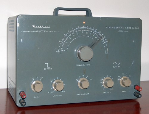
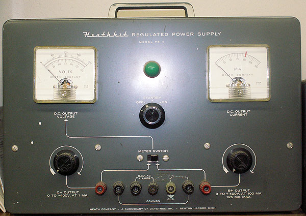
                            Oh I totally forgot that I had these. A friend of mine sent them to me and I have yet to use them for anything. Without a scope, I don't suppose the signal generator would help me any??

                            So far I've been a mult-meter and chopstick troubleshooter and it has served me well so far. Time to broaden the skill I suppose.

                            stock images but same models


                            ~Semi-No0b Hobbyist~

                            Comment


                            • #15
                              Originally posted by mort View Post
                              Without a scope, I don't suppose the signal generator would help me any??
                              Why not? If you use it to inject a signal, you can use an ac voltmeter to read the signal voltages through the different amp stages. Or you can use a second amp with a blocking capacitor lead on the input to actually hear the signal at different stages of the amp.

                              Having a scope would let you see if the waveform was being distorted, but in a lot of cases you can hear if the waveform is being distorted.

                              Comment

                              Working...
                              X