Ad Widget

Collapse

Announcement

Collapse
No announcement yet.

B100R pop on shutoff

Collapse
X
 
  • Filter
  • Time
  • Show
Clear All
new posts

  • #16
    Bias is everywhere. It means different things in different technologies. It just means some adjustment of circuit parameters to set a stable point of reference for the system.

    If you are using a jump rope, you hold the ends in your hand and swing it over your head then under your feet. If you hold the ends too high, the rope will not reach under your feet. (and might hit the ceiling) And if you hold the handles too low, the rope won't go over your head. So you hold them half way up your body so the rope passes over both head and feet. I have biased the rope handles to a point that allowed me room both directions to work.

    In your car, the engine idles when you are not moving. If you set the idle speed too low, the engine will stall out or stop running. If you set it too fast, the engine will get hotter and waste gas. So the optimal speed is 700 RPM or whatever. That too is a form of bias.

    In a solid state [power amp, we usually have two opposing power supplies, and the output transistors take turns switching on and off to drive the output positive then negative. If one side turns on before the other side turns off, excess current flows from one supply to the other through them - the amp runs hot. If one side turns off, but the other side doesn't turn on right away, there is "crossover distortion" - the output does not cross over from positive to negative, or vice versa, smoothly. The bias in the amp sets the point where the two sides hand off.


    If your pilot light jewel is blue, use a blue LED instead of red.
    Education is what you're left with after you have forgotten what you have learned.

    Comment


    • #17
      Originally posted by mtlbasslad View Post
      Mr Fahey, I think you might have the solution here, kinda neat that it's coming from the other side of the world. Wish I fully understood your solution, I'm a bit over my head here...
      If i understand correctly, bump up the resistor from 220 ohms to 2.2K and move the ground? Not sure what the ground issue is, can you elaborate? Any particular type of LED ? Also "clear high intensity RED LED" confuses me - perhaps because most pilot lights are red? In the Ampegs they are blue, but in this case it's a clear bulb in blue plastic holder.
      Ok,let's go stepby step.:
      1) pull the 220 ohms resistor,solder a 2200 ohms 1W instead.
      In fact,don't even unsolder it, so you don't even touch the PCB solder side, just cut the 220 ohm resistor legs (you'll junk it anyway) close to the body, leaving, say, 1/4"or longer "leg stumps" and solder your new resistor there.
      2) I didn't know the pilot light colour and thought it might be like the classic Fender jewel light (think Twin Reverb) which is red, but get a high intensity Blue led (or whatever matches plastic colour) and you'll be fine.
      3) don't worry about ground, clip original wires just by the original lamp
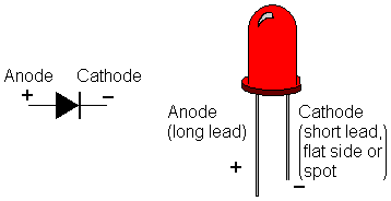
      4) filament bulbs do not have polarity, but Leds do, so solder the wire which comes from +40V (through the 2200 ohms resistor) to anode, and ground to cathode.
      Add some hot glue to fix Led to original blue plastic tube and to avoid wires touching each other and protect from vibration.

      To identify which is which:


      as you see, filament lamps can go either way, while LEDs have a "positive" which should go towards +40V and a "negative" which should go towards ground.

      Just doing that should be enough
      Juan Manuel Fahey

      Comment


      • #18
        I'll recommend Digi-key Canada as they have next day delivery (or maybe 2 days for your location) for $8. No waiting for customs like some of the other suppliers.
        Originally posted by Enzo
        I have a sign in my shop that says, "Never think up reasons not to check something."


        Comment


        • #19
          Digi-key is a good idea, thanks g-one. It would cost me $25 in gas to get to the nearest component store...
          I'm not old - I'm vintage

          Comment


          • #20
            @Enzo - thanks for the explanation, I was of course aware of bias in tube amps - just stupidly forgot that transistors are doing the same job. I guess we don't hear much about biasing SS amps because the transistors don't 'age' like tubes.

            @J m Fahey - thank you for the simplified explanation. Just wondering if I can leave the 220 ohm in place and add say 2k in the line to the LED, avoiding altering the board? Also thanks for reminding me about polarity for the LED.
            I'm not old - I'm vintage

            Comment


            • #21
              Originally posted by mtlbasslad View Post
              Just wondering if I can leave the 220 ohm in place and add say 2k in the line to the LED, avoiding altering the board? Also thanks for reminding me about polarity for the LED.
              You can certainly do that. The LED can't tell the difference. 2.2K is close enough and a standard value. The extra 220 ohm (extra 10%) left in will barely matter.
              "I took a photo of my ohm meter... It didn't help." Enzo 8/20/22

              Comment


              • #22
                Originally posted by The Dude View Post
                You can certainly do that. The LED can't tell the difference. 2.2K is close enough and a standard value. The extra 220 ohm (extra 10%) left in will barely matter.
                Thanks Dude, made sense to me. Hope Mr Fahey agrees. A-shopping we will go.
                I'm not old - I'm vintage

                Comment


                • #23
                  Yes, of course

                  That's the beauty of LEDs, they are not fussy at all about current, they will always shine between, say, 1mA and 40mA , just brighter or weaker but always visible.
                  Juan Manuel Fahey

                  Comment


                  • #24
                    Well folks, here is the update as promised.
                    Got the parts (2k2 1 watt resistor & 'clear' LED) from Digi-Key for like 59 cents (plus 8 bucks 24hr shipping, still cheaper than driving to nearest store Yay) Turns out the 'clear' LED is red...
                    Decided to check the polarity of the leads coming from the board - yep the top one is positive (+37V) - sometimes the interweb don't lie LOL

                    Fired up the new Christmas gift from eldest child (Weller WES51 temp controlled, what a difference from my 1962 model) soldered in the 2K2 & the LED... nothing exploded, 'clear' LED nice & bright RED!!... waited a few mins & switched off... guess what, still a 'crunch' although much, much less than before...

                    So, it was fun - but I still have noise (less) on shutoff. Next step, re-order CLEAR LED's & wait for 'you guys who know so much more than me' to chime in...

                    Guess I'm being a little anal here, but the original 'crunch' was really annoying, like to get rid of it completely. Small things can annoy an old fart like me...

                    Anyway, hope some of you will understand this old man's rant & help me KILL THE CRUNCH...

                    Later, Lorne
                    I'm not old - I'm vintage

                    Comment


                    • #25
                      Remember to order a clear BLUE Led, just stating "clear" is not enough.

                      As of the slight turn off thump, maybe whatever remains is not related to the pilot light any more.

                      Want to kill it for good?

                      There's a Low Tech solution which works wonders and which I always use in special cases.

                      My customers are not always heavily tatooed and pierced heavy metal guys , he he, I also get small Church Pastors, Culture Club ladies and such, the most sensitive being people from some Yoga/meditation/New Age association which often dim lights , light incense sticks, use hypnotic Music and make people concentrate or meditate .... a thump or click is definitely mood killing.

                      So in such cases I add a "Standby Switch" which is nothing more complex than an extra switch to cut the speaker out hot wire.

                      Simple instructions are: "turn Power on, count to 10, turn standby on" and viceversa when powering off.

                      Works like a charm.

                      Among others, users include a female Prison near Buenos Aires, chock full of BEAUTIFUL young women , mainly South Africans, go figure.
                      Juan Manuel Fahey

                      Comment


                      • #26
                        You may also want to try 'proving out the power switch' as a culprit.

                        With the amplifier On, gently remove the power cord from the wall socket.

                        If the noise is gone, then you have a switch problem.

                        Comment


                        • #27
                          @ JM - yeah, my stupid about the 'clear' thing... yes 'standby switch' is the ultimate solution short of a relay...

                          @ Jazz P - thing is when I first started this I disconnected one lead from the pilot light, result no pop... so it's not a switch issue...

                          Found another thread that went way over my head about the 'rails' - so I just had another drink...

                          Just wondering why I don't have the same problem on our Ampeg J12T (RI)

                          Or maybe I should find something more important to worry about LOL
                          I'm not old - I'm vintage

                          Comment


                          • #28
                            The problem is asymetrical collapse of the positive and negative power supply rails. You can avoid one rail dropping quicker than the other by connecting the LED between the positive and negative power rails instead of just the positive rail as it is. It can be connected on the positive side just as it is, at J13 but connect the cathode of the LED instead of to ground, connect it to a 4.7k resistor and the other end of the resistor connected to the junction of C38 and R66.

                            Comment


                            • #29
                              Hello Mr km6xz, I have read many of your posts & I'm flattered that you responded to this...

                              What you say makes sense to me, given what I have learned from other threads - understand, I am nowhere near your level of competence.

                              Pulled up the schematic, I see C38 & R66 can't be far from the bridge rec or the filter caps - now here's the problem - I need to take pics & post them (if I can find the damn cable) of the huge globs of silicone obliterating the component numbers. So, I'll order a 4.7K resistor & try to figure out where that junction is. My old tired eyes can't seem to find R66 (620ohms 3 watt - blue/red/black ?) maybe it's buried in silicone...

                              If I understand, C38/R66 is the neg rail? looks like that on the schematic...

                              Gotta find that cable for the camera...

                              Stay tuned for more old man rants
                              I'm not old - I'm vintage

                              Comment


                              • #30
                                Originally posted by mtlbasslad View Post

                                @ Jazz P - thing is when I first started this I disconnected one lead from the pilot light, result no pop... so it's not a switch issue...
                                Yes, but have you tried the test.
                                A negative does not prove a positive.

                                Comment

                                Working...
                                X