Announcement

Collapse
No announcement yet.

Lost inside Acoustic G120 2x12 (Model 127)

Collapse
X
 
  • Filter
  • Time
  • Show
Clear All
new posts

  • Lost inside Acoustic G120 2x12 (Model 127)

    Oh no! Hope to find my way out one day.

    Well, this works with no load attached and then with load attached it fries the 40409/40410, Q5 and Q8. They go open when you get to about half volume. I have lost two pairs dang.

    I have what I believe is the correct schematic, although it is somewhat hard to follow since part designations for transistors and diodes are mostly left blank. There aren't many voltages listed either, and it only contains preamp and power amp, not the power supply! My problem seems to be mostly in the output section, but my +/-48V supply rails also read only 41V.

    Actually I just noticed now on page 2 (the one without even resistors listed) there is a +/-43V for the power amp. But the last page list +/-48V rails. Any thoughts on how to proceed? there's a handful of confusing things going on. At this point new 40409/40410 is installed and amp passes signal but I will not attach a load again until I can confirm something.

    Acoustic G120-112 Service Manual.pdf
    Last edited by nsubulysses; 08-25-2015, 03:13 AM.

  • #2
    Originally posted by nsubulysses View Post
    Well, this works with no load attached and then with load attached it fries the 40409/40410, Q5 and Q8. They go open when you get to about half volume. I have lost two pairs dang.
    Power transistors are open or disconnected or make poor contact in their sockets, the point is they are not there to carry the main load so tiny Q5 and Q8 try to supply 100W into 4 ohms ... bang !!!!!!
    Check that power transistors show 0 ohms respect to corresponding points in the PCB, that they are not open B-E (most people check for shorts only but that's not enough) and that a few mV drop across emitter ballast resistors R23/R24 (also check resistors are not open) .

    +/- 41/42V are reasonable for that amp, *maybe* they designed transformer so it supplies +/- 48 V raw, so it drops to +/- 42V under load, a few manufacturers do that, I'd be happy with those 41V rails.

    At this point new 40409/40410 is installed and amp passes signal but I will not attach a load again until I can confirm something.
    Check what I told you first, with not functioning power transistors drivers die in seconds.
    Juan Manuel Fahey

    Comment


    • #3
      43, 48, who cares, it is forty-something, close enough.

      Are you using a bulb limiter? I suspect not, since you are burning parts.

      OK without a load? Did you check the output for DC? Each output transistor has a 0.24 ohm resistor, is either open? Also each drive has a 100 ohm resistor, same question.
      Education is what you're left with after you have forgotten what you have learned.

      Comment


      • #4
        .24 ohm resistors check good, as well as the 100 ohm R21 and R22 check good.

        I made a dumb mistake. I checked the output transistors out of circuit and did not re-insert the screw attaching them to the heatsink that also makes the collector connection.

        Now when I replace the screw and turn the amp on with current limiter the bulb lights brightly. Removing the output transistors the bulb does not light.

        I thought MJ15003 and 2N3055 were equivalent? when I put in 2N3055 the amp oscillates and the heat sink gets very hot. Original output transistors are 2SC1586.

        Thanks for your help. I been stuck on this one for a while, doing the run around because I did not put back those screws

        Comment


        • #5
          Hello nsubulysses - any chance I can get you to take some images of the preamp board of you amp? I'm working on one of theses amps and would like to see how the original grounding scheme was implemented. THX

          Comment


          • #6
            yes for sure, but look at this in case you haven't seen it. If you need anything more just let me know. Scroll to the right.

            Acoustic127t Photo by dmckeran | Photobucket

            Comment


            • #7
              Originally posted by nsubulysses View Post
              I thought MJ15003 and 2N3055 were equivalent? when I put in 2N3055 the amp oscillates and the heat sink gets very hot. Original output transistors are 2SC1586.
              Nope. MJ15003 can be used to replace 2N3055, but not vice-versa. And 3055 is a 60V part where 2SC1586 is a 200V part.
              Originally posted by Enzo
              I have a sign in my shop that says, "Never think up reasons not to check something."


              Comment


              • #8
                Not sure I saw the answer, are we working without a load? If nit, get rid of the load. Does the bulb still go bright or only with a load. Work with no load until the amp is stable and does not produce DC.
                Education is what you're left with after you have forgotten what you have learned.

                Comment


                • #9
                  Thanks those our helpful though I seem to have an earlier version = model 123

                  Comment


                  • #10
                    Working with no load as of now Enzo, thanks. The bulb lights brightly with no load with output transistors in circuit. Without them it stays very dim.

                    In my original scenario when I lost the 40409/40410s I powered on with no load and when it looked good I attached one, then lost the transistors from what appears to be no collector connection on output transistors.

                    Comment


                    • #11
                      According to ON Semi, the proper replacement for the 2SC1586 is a MJ15022G.

                      ON Semiconductor

                      Comment


                      • #12
                        Not that this relates to your fuse blowing with the amp under load - is the input jack isolated with fiber washers? I noticed that the output jacks are isolated (plastic).....

                        Comment


                        • #13
                          BTW if you keep popping the RCA 40410/09 drivers you can build your own replacements. Digi-Key sells the 2N4033 (PNP) and 2N3029 (NPN) from Central Semiconductor in a TO-5 "metal can". Same pinout as the RCA part and virtually the same electrical specifications - actually maybe better BVCEO and max collector current. I press the bad transistor out of the heatsink and ream out the hole (may be an optional step) press in the new transistor - please observe the orientation of the heatsink on the old part vs new when assembling.......

                          Comment


                          • #14
                            With the RCA 40409 and 40410 drivers, I doubt that the 2SC1586 was the original output transistor. The MJ15003 should be fine in there. Worst case with a plus and minus 45 volt power supply is 90 volts. I think the drivers are only rated at 90 volts.

                            Have you tested all of the transistors in the power amp? Most importantly Q3 the biasing transistor. I'd probably retest the outputs as well.

                            Comment


                            • #15
                              Agree.
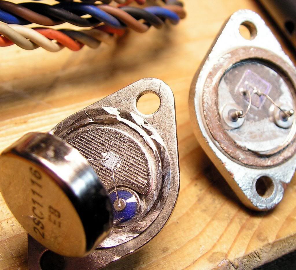
                              To begin with, those 2SC are as FAKE as a dollar printed on toilet paper.
                              One telltale sign (besides others) is the triple thickness iron TO3 base.
                              Compare regular on the left to cheap fake on the right:


                              and the reason is that since iron is such a poor heat conductor (compared to copper/silver/aluminum) , all transistors have a copper "coin", aa heat spreader inside, soldered to the iron base, while the chip itself is soldered to the spreader.
                              On the left you see a smaller chip (2N3055 size) soldered to the copper coin, which of course has 2 holes punched to allow Emitter and Base leads through; the coin itself has parallel lines engraved and you do not see it copper colour because it's tinned ... but if you scratch the surface you'll see copper below.
                              The right one has the larger die (good) but soldered straight to the iron base (horrible) .
                              Juan Manuel Fahey

                              Comment

                              Working...
                              X