Ad Widget

Collapse

Announcement

Collapse
No announcement yet.

Blue Junior Hum even with all controls at zero - help with PD, please?

Collapse
X
 
  • Filter
  • Time
  • Show
Clear All
new posts

  • #16
    Originally posted by LondonSi72 View Post
    ...The DSO Nano I have is version 2 with the BenF firmware. But I bought a separate probe that has 10x attenuation so in theory, the scope should be able to handle up to 800v. (The probes that come with the Nano are definitely not for high voltage and I wasn't going to chance hooking those up to a 300V+ amplifier circuit!)
    Simon,
    We have had previous discussions on this site regarding probing high voltage circuits using modern oscilloscopes and various probe designs. There are pitfalls that are not obvious. Rather than repeat the information here I'll refer you to one of the archived discussions at http://music-electronics-forum.com/t31492/ In particular I recommend that you note post numbers 15, 16, 21 and 22. This knowledge could save your DSO Nano from damage.

    nickb's idea about adding a couple of back to back 24V zeners or TVS diode across the scope input seems like a good idea in your case. Note that those would be placed between the DC blocking cap and the scope input.

    Cheers,
    Tom

    Comment


    • #17
      Originally posted by LondonSi72 View Post
      Partly becuase I find it hard to believe the buzz/hum I'm hearing is normal

      I don't have the equipment to properly calibrate it accurately, and I get slightly different readings each time I measure, so it's not completely reliable. I wanted the scope mainly to view the signal as it passed through the scope to see where the buzz was coming from in the circuit. I did a very rough and ready measurement against a 'known source' - a 9v battery that I could also test with a separate voltmeter and it did vary from the voltmeter reading, but I am trying to figure out a 'good' known source I can use as a calibration for it...


      The DSO Nano I have is version 2 with the BenF firmware. But I bought a separate probe that has 10x attenuation so in theory, the scope should be able to handle up to 800v. (The probes that come with the Nano are definitely not for high voltage and I wasn't going to chance hooking those up to a 300V+ amplifier circuit!)
      I gave you a method for doing this above using the heater supply so why don't you use it? You don't anything other than a couple of penny resistors. We only need to know that you are in the ballpark.

      PS: Since you are not the supplied probes in may be that the reading is 1/10th of what it should be. Also the 800V (the average probe wound handle that) only applies to DC coupling. Switch to AC and you are back to 40V ( 80Vpp//2).
      Last edited by nickb; 06-26-2016, 10:51 PM.
      Experience is something you get, just after you really needed it.

      Comment


      • #18
        PC based software scopes and tube amps?
        This might help:
        Scope Died. Anyone Use the PC-Based Ones? | The Gear Page

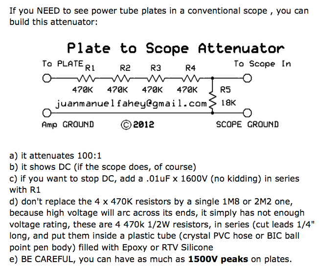
        The Internet Gods must be angry with me or just feeling bored so they hid the schematics but here they are again:
        remember the first is general purpose but the second is heavier duty, power-plate-driving-a-transformer duty approved, and meant for a real scope (or a hardware USB type) ; really way too much for a poor PC soundcard Line In.


        Juan Manuel Fahey

        Comment


        • #19
          Tom, nickb, Juan - thanks for your comments. I'm going to get my head around some of these and will get back to you. Your suggestions are really appreciated.

          Comment


          • #20
            Originally posted by nickb View Post
            I gave you a method for doing this above using the heater supply so why don't you use it? You don't anything other than a couple of penny resistors. We only need to know that you are in the ballpark.
            I don't have an electronics component store near me so have to order on-line. It takes a while for parts to arrive and there's postage costs, so I thought I'd see what else I might need before I place an order - in particular, what value capacitor for the AC coupling, for example. I did measure the heater supply voltage, though - it's 3.55vac. That's within the +/-20% of the 3.34vac that's on the BJ schematic.

            Originally posted by nickb View Post
            PS: Since you are not the supplied probes in may be that the reading is 1/10th of what it should be.
            The scope has a 1X and a 10X setting - these are used to match the probe attenuation (it's a switchable probe) - it doesn't attenuate the signal itself, it just adjusts the scale accordingly. I measured the signal at the speaker connection using the 1x values on both scope and probe, so I don't think I'm seeing 70mV as 7mV.

            Originally posted by nickb View Post
            Also the 800V (the average probe wound handle that) only applies to DC coupling. Switch to AC and you are back to 40V ( 80Vpp//2).
            This is where I got confused. I have looked at the posts that Tom pointed me to elsewhere in this forum on measuring high voltages, and I thought I understood, but you seem to be saying a 10X probe doesn't attenuate AC at all - only the DC. Firstly, is that what you're saying?

            Secondly , surely if I put the appropriate value capacitor in front of the probe to block the DC, then the 10x probe is going to attenuate the AC signal that gets passed? I shouldn't need to attenuate this as the signal isn't going to be above 80v p-p, but I just want to make sure I understand the concepts properly.

            Lastly, what value & type (metal film, ceramic) of cap should I put in front so I can see any 50Hz (and above) frequencies in the signal path whilst blocking the DC?

            Comment


            • #21
              A measurement of 3.55Vrms should give you quite a high level on confidence in your original number. The suggested potential divider would just be further confirmation but probably unnecessary. So we conclude yu don't have a noise problem, I think.

              I thought I should point out the x10 pitfall just in case as it would be an easy mistake to make.

              The probe forms a divider in conjunction with the scope. A x10 probe is basically a 9 meg resistor. If you AC couple the scope input then at DC there is no attenuation.

              If you put the DC blocking capacitor before the probe then you do divide the momentary voltage by the 10 factor. So, if you touch a 500V line you will momentarily get 50V on the scope input. The limit is 40V. The current is limited by the probe's series resistance so the damage would be limited, if any, but best not to take the chance.

              Choose in a 10nF-100nf range. The dielectric is not critical for a simple low frequency probe, it depends mainly on the fidelity I would say. Generally, polypropylene is best, then polyester and last ceramics ( there any many different ceramic types covering quite a spectrum ). You can probably get a 1KV ceramic for pennies that will do just fine.
              Experience is something you get, just after you really needed it.

              Comment


              • #22
                Originally posted by nickb View Post
                ... Choose in a 10nF-100nf range. The dielectric is not critical for a simple low frequency probe, it depends mainly on the fidelity I would say. Generally, polypropylene is best, then polyester and last ceramics...
                That fits in with my observations about coupling and other caps. The polyprops are usually brighter than the polyesters which I think means that they handle the full audio spectrum better. The polyesters are often said to be more musical, usually by the parties selling them. In experimenting with my Classic 30 in the late 90s I tried replacing ~6 coupling caps with polyester Orange Drops and got this really cool but muffled sound- very unusual! I replaced a few of those caps with polypropylene ODs and everything was perfect. So one of my mod tricks for an amp that is too bright or too dark is to change dialectrics...

                Steve Ahola
                The Blue Guitar
                www.blueguitar.org
                Some recordings:
                https://soundcloud.com/sssteeve/sets...e-blue-guitar/
                .

                Comment


                • #23
                  nickb Thanks for clarifying the 10x AC/DC coupling question.

                  As for my noise 'problem' I'm still keen to see where it's coming from. I appreciate 8-10mVrms is quiet on the basis you worked out the wattage output, but everyone who has listened to my amp asks 'is it the amp buzzing?' makes me think I'm not alone in thinking it's louder than it could be. Maybe it's the fact it's a distorted 50Hz and the higher frequencies riding on it make it sound louder than a pure 50Hz signal. (Or just as easily - maybe I'm a perfectionist

                  I've attached another sound clip - this time with me playing (not very well) through the amp at the same time. It gives more of a sense of the volume of the buzz vs the volume of the guitar. This is on a Fender Strat volume about 7 and the BJ Volume 2 and Master 5 - tones all 5, reverb 3. It's a relatively quiet piece, but it demonstrates the buzz - quiet but annoying.

                  News plus BJ buzz.m4a

                  Anyway, I've ordered a 100nF polypropylene cap with appropriate voltage tolerance to view the signal at the various stages in the amp to see if I can isolate where the sray buzz is coming from. Could be I just need to spend more on a better amp!

                  I'll keep this post updated with what I find for anyone else like me, who has a Blues Junior with hum/buzz. Still appreciate any ideas from people on the areas to check (I still need to check some Enzo suggested, and I might try that cut out Steve suggested too)

                  Comment


                  • #24
                    Originally posted by LondonSi72 View Post
                    nickb Thanks for clarifying the 10x AC/DC coupling question.

                    As for my noise 'problem' I'm still keen to see where it's coming from. I appreciate 8-10mVrms is quiet on the basis you worked out the wattage output, but everyone who has listened to my amp asks 'is it the amp buzzing?' makes me think I'm not alone in thinking it's louder than it could be. Maybe it's the fact it's a distorted 50Hz and the higher frequencies riding on it make it sound louder than a pure 50Hz signal. (Or just as easily - maybe I'm a perfectionist

                    I've attached another sound clip - this time with me playing (not very well) through the amp at the same time. It gives more of a sense of the volume of the buzz vs the volume of the guitar. This is on a Fender Strat volume about 7 and the BJ Volume 2 and Master 5 - tones all 5, reverb 3. It's a relatively quiet piece, but it demonstrates the buzz - quiet but annoying.

                    [ATTACH]39721[/ATTACH]

                    Anyway, I've ordered a 100nF polypropylene cap with appropriate voltage tolerance to view the signal at the various stages in the amp to see if I can isolate where the sray buzz is coming from. Could be I just need to spend more on a better amp!

                    I'll keep this post updated with what I find for anyone else like me, who has a Blues Junior with hum/buzz. Still appreciate any ideas from people on the areas to check (I still need to check some Enzo suggested, and I might try that cut out Steve suggested too)
                    BY some amazing piece of irony I've been listened to that same Mark Knopfler piece many times today as I tried to induce a PA with an intermittent to go wrong....and then I got a bonus YOU playing it. You do it better than I can.

                    What I hear is more a buzz as opposed to hum. This is usually associated with the switching spikes from the rectifiers. Quite a low level can be really annoying. It can also be tricky to get rid of. Lead dress, bad grounding are common causes. You can try changing the rectifiers to fast types such as UF4007 or add small capacitors across them.

                    Addendum: I recall you said that the control don't affect it but pulling the PI does. It could be coupling into the PI via the grids or from the heaters. Try a different a tube to eliminate the heater path.
                    Last edited by nickb; 06-30-2016, 11:21 PM.
                    Experience is something you get, just after you really needed it.

                    Comment


                    • #25
                      Yep, the buzz is certainly excessive when you are playing. One question that you've probably already answered: does the buzz get louder when you turn up the amp volume?

                      This is not meant as an insult but sometimes it is worth it to pay a good amp tech to diagnose the problem. I have a hunch that once he finds the problem the fix will be pretty easy (like a poor wire connection.) I assume that you have tried unplugging all of the connectors and plugging them back in. I would also set my DMM to check continuity between chassis ground and the various grounds you'd expect to find after studying the schematic and layout drawing.

                      Steve Ahola
                      The Blue Guitar
                      www.blueguitar.org
                      Some recordings:
                      https://soundcloud.com/sssteeve/sets...e-blue-guitar/
                      .

                      Comment


                      • #26
                        Originally posted by nickb View Post
                        BY some amazing piece of irony I've been listened to that same Mark Knopfler piece many times today as I tried to induce a PA with an intermittent to go wrong....and then I got a bonus YOU playing it. You do it better than I can.
                        Thank you I love Knopfler - he has a fantastic touch and makes simple sound amazing. Closest 'amateur' I've heard who gets any where close to the sound is Stefan Price - he has a few videos on YouTube if you're interested.


                        Originally posted by nickb View Post
                        What I hear is more a buzz as opposed to hum. This is usually associated with the switching spikes from the rectifiers. Quite a low level can be really annoying. It can also be tricky to get rid of. Lead dress, bad grounding are common causes. You can try changing the rectifiers to fast types such as UF4007 or add small capacitors across them.

                        Addendum: I recall you said that the control don't affect it but pulling the PI does. It could be coupling into the PI via the grids or from the heaters. Try a different a tube to eliminate the heater path.

                        Thanks for the pointer. One of my earliest tests was buying a new set of tubes and switching them around, but it didn't seem to affect the buzz. But after reading your pointer I had a look around for other posts on rectifier buzz in amps and found a useful post in another forum (Fender buzz? - UK Vintage Radio Repair and Restoration Discussion Forum) where the guy had similar(ish) sounding problems and resolved by converting the heater supply to DC by adding a bridge rectifier. Bill Machrone, who's a bit of an expert on Blues Juniors (billmaudio.com) had tried this but said it didn't improve his amp much and the rectifier got hot/added a big load on the PT, so I've replied to the guy who wrote the post on the other forum to see if the fix lasted...

                        I also had another look around the amp with the scope again (I got a 100nf capacitor from RS-components on free next day delivery - bargain!) with a 1kHz 10mVrms sine wave signal input as the Fender schematics suggested and I'm pretty much getting the voltages they suggested, so I think that side is good. But I noticed the PI has a slightly distorted 50Hz signal on both anodes. Not sure if that indicates coupling to the heater. It's only 13mVrms, but then so is the buzz on the output...

                        See below:

                        Click image for larger version

Name:	PI input BJ.JPG
Views:	1
Size:	1.09 MB
ID:	842370


                        I also saw a small (5mVrms) but distinctly noisy signal on the second stage gain tube input that looks like it's 100(ish) Hz. Hard to trigger on it as it was drifting.

                        Click image for larger version

Name:	Sexond stage gain tube anode.JPG
Views:	1
Size:	1.16 MB
ID:	842371

                        Comment


                        • #27
                          DC heater elevation is a technique that has most benefit when dealing with 50/60Hz hum especially in the low-level signal stages near the input jack. DC heaters do much the same but it does put a big strain on the power transformer.

                          The AC on the PI anodes is not an issue unless they are of opposite phase. You would need a two channel scope to see that.

                          Be very suspicious when measuring tiny signals. You have you be very careful in your measurement technique as pickup in the probe leads or a poor choice of grounding can give misleading results.

                          You already know the problem is after the master volume so any stage before that is off the table. And, if the master at zero and you pull the PI the hum/buzz goes away, that rules out all the stuff after the anodes.

                          Try eliminating the PI grids: First solder your new shiny 100nF cap from V4 pin 2 to ground - the grounded end of C13 would be a good one to choose. Next try soldering it to V4 pin 7 instead keeping the ground the same. Any improvement?
                          Experience is something you get, just after you really needed it.

                          Comment


                          • #28
                            I just posted this on another thread but a quick'n'dirty way to see if converting the heaters to DC will help with a noise issue is to connect the filament leads to a 6vdc lantern battery (or a 4 cell battery holder with D or C cells.) As I recall when I disconnected the AC filament supply as a test the heaters stayed hot enough for me to hear if the noise was eliminated before the sound faded away.

                            Quick'n'Dirty is my motto... who needs an oscilloscope when you already have a good pair of wire cutters?

                            Steve Ahola
                            The Blue Guitar
                            www.blueguitar.org
                            Some recordings:
                            https://soundcloud.com/sssteeve/sets...e-blue-guitar/
                            .

                            Comment


                            • #29
                              Thanks again nickb.

                              OK - so some useful results from today's latest test

                              I did as you suggested, and connected the 100nF capacitor from the PI tube (v3, not v4) pin 7 to ground and ... no buzz! However, the amp also lost a huge amount of volume and lots of treble - I could wind up both Volume and Master to full and strum the guitar without having the neighbours call the police.

                              Doing the same thing with pin 2 had no effect. So - an interesting result, but not sure what that means for a solution to the problem...
                              Last edited by LondonSi72; 07-05-2016, 08:48 PM.

                              Comment


                              • #30
                                Originally posted by Steve A. View Post
                                I just posted this on another thread but a quick'n'dirty way to see if converting the heaters to DC will help with a noise issue is to connect the filament leads to a 6vdc lantern battery (or a 4 cell battery holder with D or C cells.) As I recall when I disconnected the AC filament supply as a test the heaters stayed hot enough for me to hear if the noise was eliminated before the sound faded away.

                                Quick'n'Dirty is my motto... who needs an oscilloscope when you already have a good pair of wire cutters?

                                Steve Ahola
                                I was wondering about rigging up a simple alternative 6vDC source for the heaters, but as the AC source is 2.5A I didn't think regular batteries would have anything like enough power to be a valid test. I have a whole host of variable output 'wall wart' DC transformers for various gadgets that have 6v settings, but again these are all 300mA output type devices, and I didn't think they'd be suitable.

                                Looking on a RS-Components - my new best friend - they have bridge rectifiers for a few pounds, and a 4700uF capacitor is pretty cheap too, so it might be almost as cheap to build a unit for testing...

                                Comment

                                Working...
                                X