Ad Widget

Collapse

Announcement

Collapse
No announcement yet.

Marshall 2098 Running Hot

Collapse
X
 
  • Filter
  • Time
  • Show
Clear All
new posts

  • Marshall 2098 Running Hot

    Hey Guys ...

    I have a Marshall 2098 solid state amp running HOT at idle (almost too hot to touch without signal).

    The lay of the land:

    The output transistors are: MJ15022/MJ15023 (replacing the MJ3001/MJ2501 pair).
    The BC182 was replaced with a 2N3904
    The BC212 was replaced with an NTE193
    The BC184K was replaced with a 2N3904

    Also, the two 470 ohm resistors were replaced with pots to be adjustable (this was a later factory engineering change).

    Voltages on MJ15022 (NPN - MJ3001 replacement):
    Vc = +38V
    Vb=0.95V
    Ve=+.29V

    Voltages on MJ15023 (PNP - MJ2501 replacement):
    Vc = -38V
    Vb= -0.85V
    Ve=-.28V

    Note: Voltages measured with respect to ground, the auto transformer removed from the circuit and with no speaker connected).

    Also, I am measuring about .275 volts across the .33 resistors (which seems very high).

    I am suspicious of the mismatch between the NTE193 and the 2N3904; I was thinking of replacing the NTE193 with a 2N3906 to make them a little more matched.

    Anyone have any ideas how to attack this (and/or why this is happening)?

    Thanks

    Click image for larger version

Name:	2200-pwr.gif
Views:	1
Size:	392.7 KB
ID:	870816

  • #2
    Hi
    Well, what possessed you to replace the darlington MJ3001 with the plain bipolar MJ15022? That is the problem right there.

    Here:
    http://freenrg.info/DataSheets/MJ3001.pdf

    Since a darlington is two transistors stacked, the base will be biased at two junction drops above the emitters. If you stick a single transistor in its place, not the base of that transistor is overbiased by a factor of two. The bias is adjustable, but I doubt it has the range.

    Also, the darlington has much higher gain than the MJ15022, so even if you can bias it up, I don;t know how well it would perform.

    The MJ3001 is obsolete, though someone may have some. Darlingtons in a TO3 are not that common, though here is a possible candidate, in stock at Mouser
    http://www.mouser.com/ds/2/308/2N6284-D-102932.pdf

    BC212 and BC184 are just limiters and probably not involved, but each can be disabled by disconnecting the diode associated with it.
    Education is what you're left with after you have forgotten what you have learned.

    Comment


    • #3
      This was already discussed in:
      http://music-electronics-forum.com/t37236/

      and this is what renkus Heinz has to say:

      Unavailable TO3 metallic transistors can be replced with modern plastic TO218 or TO247 packages, with a little leg bending to fit original hoes.
      In that case you must use Darlington TIP142/147 instead of the original ones.
      By the way, what Marshall itself did in later models, first house labelled BDV64/65 if I am not mistaken , and then 142/147 .
      Read all about it here: http://music-electronics-forum.com/t37236/
      and this is what Renkus Heinz had to say about it:
      Replacing TO-3 output devices in older amplifiers

      It is a problem replacing TO-3 devices as many are no longer available. However, electrically equal or superior devices are available in plastic “tab” packages like the TO-218. The large format plastic package of devices such as the 2SC1302 are meant to mount in locations where TO-3 devices were formerly used.

      In order to replace TO-3 devices with a large format tab device you need:

      - A suitable TO-218 or similar device. In the case of the RH D1500, this device needs to have a Vceo of 200V or better and an Ic of 15A or better

      - An insulator washer for that replacement device. The old TO-3 one will not be suitable.

      - In the case of a transistor where the mounting hole is not in a bare metal tab but is surrounded by plastic, you may need a solder lug where the mounting hole area is round and flat, not toothed.

      To mount the replacement device you must:

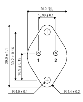
      - Bend the base and emitter leads (the two outer leads) 90° down exactly where the lead steps down in width so that the distance between the center of the mounting hole to the lead is 0.665” or 17mm
      - Replace the TO-3 insulating washer with the new one. The alignment is such that the large hole in the washer will be around the TO-3 mounting hole furthest from the emitter and base leads.
      - Insert the transistor. Note that at this time, the collector, or center lead will still be attached to the transistor and will not be bent. Be careful inserting the emitter and base leads as they are square or rectangular and the old leads were round. If a socket was used for the TO-3 device, you may have to force it a little and you may have to solder the pins in place to get a reliable connection.
      - If the replacement device has an exposed metal tab, use the mounting screw you used for the TO-3 device to make the electrical connection for the collector. Then you can snip off the collector lead from the transistor. Please note that in some cases, the TO-3 device may have been connected to the other mounting hole. If this was the case, you may have to solder a short piece of insulated wire between the two mounting points of the TO-3 device.
      - If the replacement device does NOT have an exposed metal tab and the mounting hold is surrounded by plastic, you may need a longer mounting screw. You will need to solder a flat solder lug to the collector lead and bend it over the top of the case so that the hole in the lug lines up with the mounting hole so that when you put in the mounting screw, the collector connection may be made. Please note that in some cases, the TO-3 device may have been connected to the other mounting hole. If this was the case, you may have to solder a short piece of insulated wire between the two mounting points of the TO-3 device.

      If you have any questions about this, please contact the engineering dept. at Renkus-Heinz

      Dan Fraser
      July 12, 2001


      Notice Reinkus heinz trusts the TO247 leg width change point as reference where to bend legs down, I do not because it depends on brand, so I suggest you place the new transistors on the heat sinh, still as received, place the transistor hole over the proper heat sink hole (the one more separated from BE legs) and with a fine tip Sharpie or equivalent mark the actual bending point, which should be 17mm from the mounting hole.
      Since TO247 which I recommend has a fully insulated top, the mounting screw will NOT connect transistor collector (which in TO3 was the case) to the track on the PCB, so youīll need to add a terminal on top which will be mechanically pressed by the screw but wonīt make electrical contact (plastic case) and bend and solder the collector leg.

      No big deal, easier done than said.
      Maybe later Iīll take and post a picture of a "converted" TO 247.
      Juan Manuel Fahey

      Comment


      • #4
        Enzo and Juan - Thank You!

        I checked and Newark.com is selling the MJ3001/MJ2501 transistors by MultiComp in the T03 package; so I order them.
        If I could not get them in the T03 package, I would do the TO247 conversion.
        It was strange that despite the heat sink being very big for two T03 transistors, got as hot as it did (compared to a Sunn Coliseium bass - similary size but more transistors).

        Also, as Enzo said, the adjustment pots had no effect on the transistors what so ever.
        The amp had blown outputs and the center of dual rail supply was not connected to the board causing
        one of the the low voltage zener diodes to blow (and it failed shorted when I got hold of it).

        After 40 years, it was due for an overhaul and proper setup ...

        Again, thank you for the info ....

        Comment


        • #5
          Additional Transistor Help!

          OK - the Multicomp MJ3001 and MJ2501 transistors arrived. I removed the MJ15022/ MJ15023 and put in the correct transistors.
          Now when I apply power - the MJ2501 blows open emitter to base and I end up with +38 volts on the rails.
          However, the MJ15022/ MJ15023 pair did NOT fail and produced output.
          With a quick check, the surrounding transistors and diodes meter out OK. The .33 ohm resistors are not open.

          Is it possible that the MJ2501 were defective?
          Am I missing something; Any ideas on how to tackle this?

          Comment


          • #6
            You need a light bulb limiter to finish trouble shooting your issues. What does the amp (power supply) do with no output transistors in the circuit? Multicomp is not a supplier/producer of anything they are really a distributor of sorts. Did you buy more that one TO-3 PNP - if so how does it measure out of circuit? If you must have hermetic package try buying from Central Semiconductor.
            Last edited by gbono; 08-16-2016, 08:50 PM.

            Comment


            • #7
              Thanks for the reply ...

              The amp did not blow the fuse; just the transistor (Emitter to Base - open).
              So I guess (key word) that it is related to the MPSA06 transistor feeding it.
              Also, not sure if 1K pot/2.7K resistors feeding the base of the the BC184K have anything to do with it.
              I bought 3 of the transistors. First one blew on power-up.
              I checked the second one before installing it and it metered out correctly. On power-up it too blew in the same fashion.
              None of the small transistors or diodes appear to be shorted.

              I also have the auto transformer disconnected for the purposes of checking the DC offset (now + rail voltage).

              Help Please!!!!

              Comment


              • #8
                I am still for the idea suggested to use the light bulb limiter after changing out parts. Hence transistors blowing out might be prevented using bulb limiter. Also, I hope you don't have a speaker load connected to the amp!! Just saying since you said at one point "it produced output", just got to be sure. When you said "First one blew on power-up." which transistor is that?
                When the going gets weird... The weird turn pro!

                Comment


                • #9
                  1) use the light bulb limiter and load it with a small bulb, say 25W

                  2) no load at all on the output, I know you disconnected the transformer but do the sme with the speaker or anything else.

                  3) you DID blow a fuse, although not a visible one: power transistors are actually 5mm per side silicon squares, they look like you cut piece of insulating mica with scissors
                  The "die" is soldered to transistor case which is the collector and is connected to emitter and base through copper wires, usually rated for 15A

                  they often blow ... which is good.
                  You measure B to E open ... which is actually true.

                  4) before putting the new transistors in place, measure BE for both.
                  They *may* be way overbiased which will blow them.
                  From another thread which also discusses Darlingtons, Vbe should be around 1100 to 1200mV, not higher ...post what you find.

                  5) we canīt discard the possibility that those 2501/3001 pairs are as fake as a rubber dollar coin.
                  In that case consider getting two pairs of TIP142/147
                  Juan Manuel Fahey

                  Comment


                  • #10
                    Strangely, the incorrect transistors did produce output (MJ15022/MJ15023) solid and loud; but generated a massive amount of heat.
                    Ordered the correct transistors, assuming the rest of the circuit was correct and functional (being as I had strong output).
                    I figured that I was going to pop it open, change the 2 output transistors to the correct type (MJ3001/MJ2501) and all would be well!
                    Instead, the the MJ2501 blows open (but does not short - kind of strange).
                    Based on this circuit, can I power this up with the output removed and have it blow up?

                    Also, the first time it blew, a load was connected (but the auto transformer was not connected).
                    The second time it blew, no load was connected ....

                    Only the (MJ3001/MJ2501) set had the issue. The MJ15022/MJ15023 set never blew (with or without the auto transformer connected).

                    Comment


                    • #11
                      Just to clarify: The main 4A Slo-Blow (verifed as the correct value for the amp) fuse never blew; only the mj2501 transistor.

                      I will try to measure the Vbe voltage later and report back ...

                      Thanks ...

                      Comment


                      • #12
                        Well, they might be fakes, while the MJ ones are good ones.
                        Just speculating.

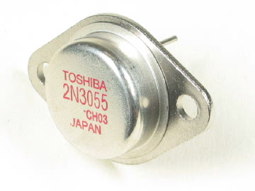
                        I got bit (until I had to learn to work around them, since they are the easy to find ones) by "Toshiba" 2N3055.

                        Funny thing is, the dies are good !!!!!!!!

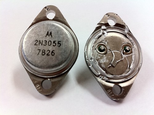
                        But metallic TO3 are usually made out of steel, which is thermally poor, so internally they solder a thick copper "coin" , with two 4mm holes punched in it to allow for the exit wires for emitter and base (collector is soft soldered to case)
                        These are good ones, look at the copper coin and the die size, you get what you pay for:


                        This is what fake Toshiba uses, a puny excuse for a copper heat spreader:

                        į
                        These are as poor but use a different trick, they punch a round hole in the case and press a small copper disk inside it:


                        These are the worst, by far, they solder a TIP31/32 sized die straight to the steel case:


                        They "try" to compensate by making the steel base triple thickness ... not enough:


                        Often, the poor quality chip is covered in what most think is white thermal grease, but itīs actully a drop of white Epoxy.
                        Might suspect they are not even soldered to the steel base but plain epoxied to it.

                        Worst is that many of the dies in general are good , but lack of thermal transfer kills them quickly.

                        If you didnīt drop your dead transistors in the junk bin, and feel so inclined, you might cut/file/crush open one and show what you relly got .

                        On some, the hat/cover pops out easily with some pressure from a gas/water pipe plier .
                        Juan Manuel Fahey

                        Comment

                        Working...
                        X