 Tweet
Tweet
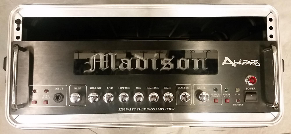
I've had 2 different bass amps do this lately. This one is a Madison Abraxas amp that had a blown up output stage, as someone ran the output of another amp into this amp's output. The amp runs 2 power amp stages in bridged mono for 800W at 4 ohms. I fixed the blown output stage, but now it has a bad buzz on the speaker output. It looks like its 60Hz but there is another small notch in between them. I'm seeing notches that match the buzz on the HV rails and to a lesser extent on the 15V rails. Grounding the return jack doesn't change the output, nor does turning the Master Volume all the way down. The scope pic below has the speaker output on the top trace and one of the HV rails on the bottom trace. I tried a new bridge rectifier on the HV supply, but that did not change anything. Will putting caps across the rectifier diodes smooth the notches out? Or, is there something else that I need to check? Schematics below:

-
-
The two links are dead. -
-
Have you tried temporarily lifting R52 (zobel resistor)?Comment
-
Not sure those schematics match your amp
The Abraxas Madison is a 6 band graphic EQ, 2 x 600W bridgeable power amps for 850W into 8 ohms, 1200W into 4, and claims being a "tube amp" which at least should mean a token 12A*7 in the preamp.
It even has a tube bypass switch.
Schematic posted shows a no tube anywhere 9 band EQ, and a presumably 300W single power amp ...... which by the way is called SB300 in the schematic.
It�s signed by chang yue something which most probably is an OEM manufacturer for **a lot** of brands.
FWIW they might also make the Abraxas, just that this is not the matching schematic.Juan Manuel FaheyComment
-
This might be a later version. The power amp schematic only shows one of the power amp stages. If you look on the upper right, it shows that it is hooked up in bridged mono with another power amp B section. They only show you the A section in the schematic.Comment
-
-
Ok, now I see it.Originally posted by rf7 View Post
Bridged amps inverter is on the preamp, in this version signal comes from IC105a (might be called same number or not in yours, not the main point, only function matters).
Try unplugging ribbon or shielded cable from connector SCN3 at the power amp end.
Just incase doing so leaves preamp without ground connection, momentarily add a plain wire from board to board ground, from SCN3 (power amp) to CN3 (at the preamp).
What happens?
Other tests may be to leave connectors plugged in at both ends but consecutively short R183 - R186 (preamp) - R2 (channel A) - R??? (same function) channel B.
Any change?
Are both power amps on the same large PCB or it�s kludged out of 2 (stacked or side by side) separate PCBs?
Not dissing anybody, I bet they sell *a Ton* of 300W amps and WAY less 800/1200W ones, so it�s a sensible approach to accomodate some special customers.Juan Manuel FaheyComment
-
Change driver transistors too, inspect pcb for broken traces, especially ground.
Try running just each output against ground (not a brigde) and see what happens.Comment
-
I just did the latter test, as it was easier. Grounding either one of the power amp inputs increases the hum quite a bit. Grounding both completely eliminates the hum. Looks like the preamp/power supply PCB is the culprit then, right?Originally posted by J M Fahey View Post
It's kludged out of 2 PCB's. And, by the way, the schematics are for different versions of the boards, but they are close enough. The preamp & power amp are on one PCB; there are 2 power amp PCB's on one heatsink, and there is a Rear Jack PCB.Originally posted by J M Fahey View PostComment
-
I forgot something. One of the 15V rail caps, C24 blew up in the original amp failure. I replaced it along with C25. Could the regulator IC2 be compromised because of that?Comment
-
Yes, I changed the driver transistors. When I ran each amp against ground, the amp that I just fixed was ok, whereas the one that I did not fix had the buzzing on it's output.Originally posted by darkfenriz View PostComment
Comment