Ad Widget

Collapse

Announcement

Collapse
No announcement yet.

Seeking Advice: Ampeg V-4B PCB Trace Liifting

Collapse
X
 
  • Filter
  • Time
  • Show
Clear All
new posts

  • Seeking Advice: Ampeg V-4B PCB Trace Liifting

    Hi folks I own a 1972 Ampeg V-4B tube Bass Amp. I recently completed a cap job. While in the amp I noticed that a PCB trace from Input 1, to PCB board is lifting. The connection is seen in the centre of the pic here. The wire wrapped in white/clear covering. It attaches to the board as seen, and then the trace travels over to V1, pin 7.

    The connection seems to still work fine, however I am thinking it may get worse in time. Should I consider repairing this PCB trace? I have never done this type of work before on a PCB.
    I was thinking I could maybe also lift the wire and directly solder it to the V1 socket connection at pin 7.

    Your comments are appreciated.


  • #2
    Originally posted by keithb7 View Post
    The connection seems to still work fine, however I am thinking it may get worse in time. Should I consider repairing this PCB trace? I have never done this type of work before on a PCB.
    I was thinking I could maybe also lift the wire and directly solder it to the V1 socket connection at pin 7.
    I have only fixed a lifted pad on a circuit board once successfully using epoxy and it was a pain in the ass (never tried again). Your idea to solder it straight to pin 7 seems like a good one to me. Also, there is that unused connection between the two points...? Cut the trace on that unused pad's connection and solder a bridge from that new one to the pin 7 connection.
    Click image for larger version

Name:	Screenshot from 2017-09-13 13:41:42.png
Views:	1
Size:	810.6 KB
ID:	846417
    Last edited by DrGonz78; 09-13-2017, 09:11 PM. Reason: add a picture
    When the going gets weird... The weird turn pro!

    Comment


    • #3
      Originally posted by DrGonz78 View Post
      I have only fixed a lifted pad on a circuit board once successfully using epoxy and it was a pain in the ass (never tried again). Your idea to solder it straight to pin 7 seems like a good one to me. Also, there is that unused connection between the two points...? Cut the trace on that unused pad's connection and solder a bridge from that new one to the pin 7 connection.
      [ATTACH=CONFIG]44893[/ATTACH]
      Isn't that a pad for R4? Also, is it just me or does the solder on the right end of C2 look a bit suspect?

      Comment


      • #4
        Originally posted by glebert View Post
        Isn't that a pad for R4? Also, is it just me or does the solder on the right end of C2 look a bit suspect?
        Yeah it does connect to R4 but to me it appears that R4 is missing anyway. Disregard my idea if R4 is connected or has double sided connection point. Yeah there is too much solder on that C2 connection point.
        When the going gets weird... The weird turn pro!

        Comment


        • #5
          I like the idea of soldering directly to the tube pin. My $.02.
          "I took a photo of my ohm meter... It didn't help." Enzo 8/20/22

          Comment


          • #6
            Is that R1 spot loaded? If so, you must maintain that connection to pin7. There must be some grid leak resistor either there or at the jack?
            Do you have an accurate schematic for this particular board version? The '71 schematic calls the grid leak R2, not R1.
            Originally posted by Enzo
            I have a sign in my shop that says, "Never think up reasons not to check something."


            Comment


            • #7
              Another vote for direct connexion to tube socket pad.
              This isn't the future I signed up for.

              Comment


              • #8
                Never mind (post #6), R2 must be at the jack. The same board is used in the V4, where R1 and R4 are in use.
                You can move the wire right to pin 7, as others have mentioned.
                But you should also address the reason this occurred in the first place, lack of strain relief where the wire meets the board.
                Originally posted by Enzo
                I have a sign in my shop that says, "Never think up reasons not to check something."


                Comment


                • #9
                  Sorry I should have mentioned the board does appear to be shared with the v-4 guitar amp. Mine is the V-4B.
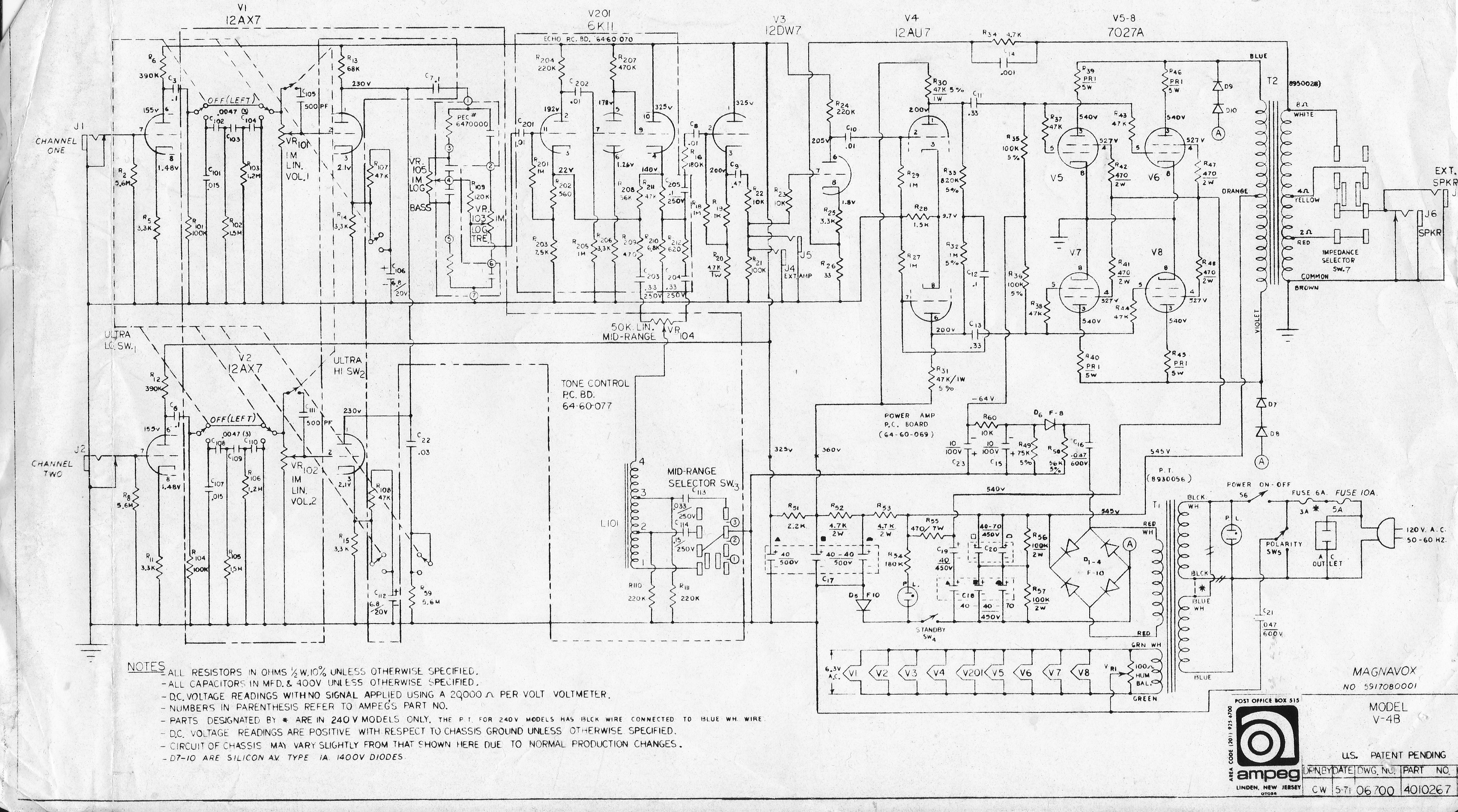
                  Here is an accurate schematic for my amp. I will consider attempting to wire directly to the socket pin 7, and support the wire with some type of anchor.
                  I see R2 in the schematic is tied to V1 pin 7 as well. I can't see an R2 anywhere on my board.
                  Thanks, Keith

                  Comment


                  • #10
                    I wouldn't hesitate to solder the wire direct to the tube socket pin.
                    Education is what you're left with after you have forgotten what you have learned.

                    Comment


                    • #11
                      Usually I just scrape a lifting trace clean with a fiberglass pen and solder a length of stripped of appropriate sized copper solid core wire over it with a little flux and clean it up with alcohol. If I want to make it pretty I brush on a little clear lacquer. If it's a big trace I use braid.

                      Comment


                      • #12
                        Originally posted by keithb7 View Post
                        I see R2 in the schematic is tied to V1 pin 7 as well. I can't see an R2 anywhere on my board.
                        I think R2 (and R8 for ch.2) are probably mounted at the input jacks?
                        What did you use to replace C18,19, & 20, all discrete caps?
                        Just a warning that C19 & 20 have their negative terminals at over 250VDC, so you don't want any caps that tie their negative to the shell there (shock hazard for wandering hands).
                        Attached is the service manual (excluding schematic) in case you don't have it.
                        Attached Files
                        Originally posted by Enzo
                        I have a sign in my shop that says, "Never think up reasons not to check something."


                        Comment


                        • #13
                          check the pads for the screen resistors also

                          Comment

                          Working...
                          X