Originally posted by g1
View Post
Ad Widget
Collapse
Announcement
Collapse
No announcement yet.
grounding load box w/BNC jack for 'scope?
Collapse
X
-
Comment
-
Wouldn't ya' know, in a moment of "I have too much shit around here", I tossed (or gave away) a couple of pamona BNC to banana jack adapters during a shop purge. I haven't been burned for the most part doing that in the past, but, perhaps I should have made some room for those and held on to a couple.Originally posted by Enzo View PostAside from regular scope probes, I had a few BNC to BNC cables for my scope, and I had BNC female to dual banana male adaptors. For that matter I have BNC male to dual banana female binding posts.If I have a 50% chance of guessing the right answer, I guess wrong 80% of the time.
Comment
-
You know, I would toss those project of the future amp carcasses or whatever to make space, but tools and adaptors... never.
I probably should clean house now, I still have adaptors made for pinball machine CPU boards and dollar bill changers.Education is what you're left with after you have forgotten what you have learned.
Comment
-
FWIW: I find nothing in that article that convinces me to change my opinion. Quite the opposite. Of course you should check for AC-chassis leakage before you send something out the door, but that's not a reason for abandoning the isolation transformer. You can check for leakage with a meter, or find out with your fingers. I prefer to be safe. Of course, it still requires some common sense. Just because you're isolated doesn't mean you can't get a jolt.Originally posted by SoulFetish View PostHere is an article which makes a good case for not using an isolated transformer in many instances:
Isolation Transformers"I took a photo of my ohm meter... It didn't help." Enzo 8/20/22
Comment
-
What do you guys think about this configuration for a load box..
• 3 switchable taps for 4Ω, 8Ω, & 16Ω
• 300W max dissipation for each load impedance
• using 3 resistors total (ish)
Here is the wiring diagram:
The challenge is the simplest, most efficient way to switch in and out of this. Any thoughts?
edit: I made a mistake, the 8Ω tap will not be able to dissipate 300W. If my math is correct, it will be able to dissipate ≈150W. right?Last edited by SoulFetish; 10-24-2017, 03:06 AM.If I have a 50% chance of guessing the right answer, I guess wrong 80% of the time.
Comment
-
That's what I got too. 25W per 50 ohm leg and 50W per 25 ohm leg in the 8.33 ohm configuration.Originally posted by SoulFetish View Postedit: I made a mistake, the 8Ω tap will not be able to dissipate 300W. If my math is correct, it will be able to dissipate ≈150W. right?
And your 4.16 ohm drawing is missing one of the connections along the bottom.Originally posted by EnzoI have a sign in my shop that says, "Never think up reasons not to check something."
Comment
-
As much as I like the idea of using 3 physical resistors to build it, I really don't like loosing half power handling for one load impedance. I'm probably not going to need 300W all that often, but I want to build something once and build it right. So I decided to change it, and simplify the switching. Plus, I bought nice aluminum enclosure for short money and the big 100W wouldn't fit without physically modifying their mounting brackets. I'm using this configuration. 4,8, and 16Ω loads all just a bit under 300W max. Here is a layout to scale:
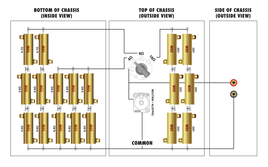
I didn't want to get unbranded Chinese resistors off ebay just to save money without any access to information about the part. I was able to get these most of these 50W wirewound from Newark for under $2 a piece and didn't pay more than $3 for any of them.If I have a 50% chance of guessing the right answer, I guess wrong 80% of the time.
Comment
-
Here is quick build update, incorporating the helpful advice I received:
(plus one quick question)
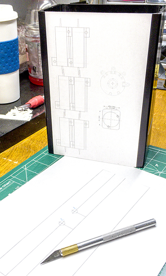
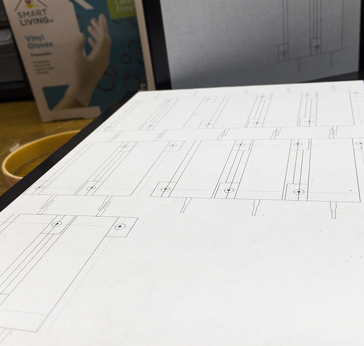
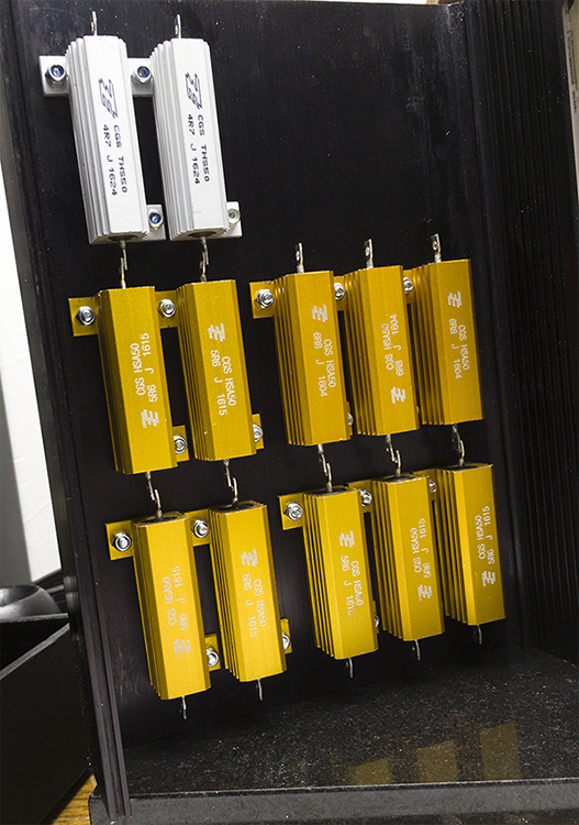
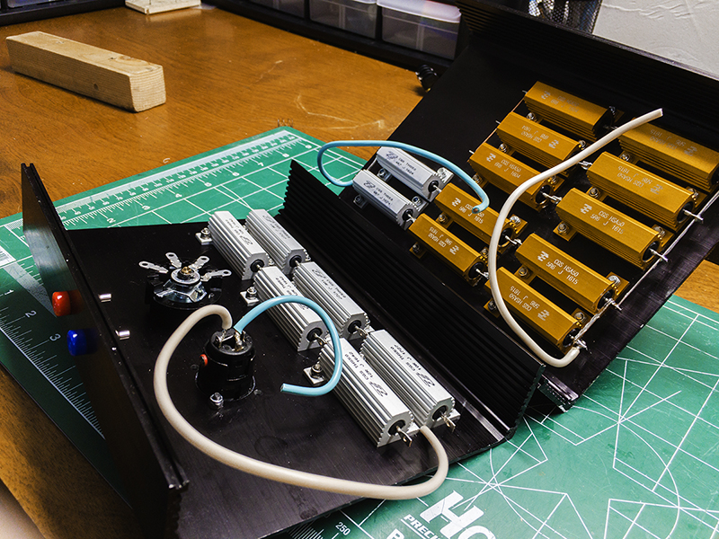
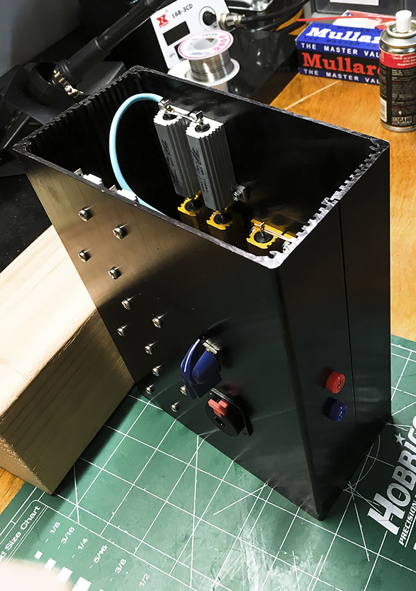
This should give me close to 300W per tap. I built this to be switchable for 4, 8, and 16Ω, however, I've worked on a few old 'Supers since I designed it and ordered the parts for it. So, here is my question:
Do you guys often have need for 2Ω loads? (or often enough?) If so, I was thinking the easiest solution would be to switch all three into a parallel configuration - ie. 1(1/4+1/8+1/16) = 2.2857. That's pretty close. Anyone see any issue with that?
I wanted to leave the extra room to have the flexibility to install a speakon and/or banana input jack later on if I need to. The only change I would need to make is replacing the current switch with a 4P4T(minimum) rotary switch.If I have a 50% chance of guessing the right answer, I guess wrong 80% of the time.
Comment
-
Close enough. Aside from big PA type power amps, you won't have much need aside from Supers.Originally posted by EnzoI have a sign in my shop that says, "Never think up reasons not to check something."
Comment
-
My main load bank is configured as (8) 4 ohm/500W Dale Power resistors (pair of 2 ohm 1% Non-inductive 250W resistors in series, four channels per large fan-cooled heat sinks, terminated in isolated dual banana jacks, all spaced on 3/4" centers, so I can configure my loads as 1 ohm/2kWz, 2 ohm/1kW, 4 ohm 2kW or 4 ohm 500W, 16 ohm/2kW per channel, Or 2 ohm/4kW using all 8 loads. And, other variations as req'd. I also have a smaller load panel that's 4 ch of 8 ohm/200W that's portable.
My scope normally is connected thru my Amber 3501a Audio Analyzer's Monitor BNC's, with the input to the analyzer via differential input. Generator output can be grounded or transformer isolated via HP 353A Transformer/Step Attenuator Patch Panel. I use a variety of signal sources...Sine, Sine Random, Pink Noise, Burst pink noise, 1/3 oct Pink Noise, Swept Sine, Square Wave, two-level tone burst Sine, etc.
If I need to go probing, I can do it with X10 scope probe, usually directly grounded, but not always, depending whether I have the Analyzer's input attached to the gear being measured. I have differential plug-ins for my Tektronix 7633 scope when needed. If I"m using a spectrum analyzer, I have two that are balanced....one via xfmr, the other via differential inputs. Also have a good bridging input transformer for my B & K analyzers/measuring amps.
My load banks are normally directly connected to the outputs if using dummy load, or may be test speaker. I normally monitor the output thru the Diff input of the Amber 3501a Audio Analyzer. I also have a Valhalla 2101 set up with a patch panel that can be used to directly monitor the power output of amps under load, be it dummy load or speaker load. The instrument is a wide bandwidth true RMS meter that also measures DCV.
My main metered variac is connected to a 5kW Topaz Isolation transformer. If I have to go probing into an amp's switching power supply, I have a vintage Sony/Tektronix 326 battery powered scope so I can be totally isolated.Last edited by nevetslab; 12-06-2017, 07:59 PM.Logic is an organized way of going wrong with confidence
Comment
-
One load that I've never built is a dummy reactive load that closely resembles that of a speaker in both a sealed box as well as in a port-tuned box. Does anyone out there have details on building one? My shop space is down the hall from three of our rehearsal studios, one of which I share the walls with. When I'm power-testing an amp that has issues driving a speaker without having drive problems , the SPL levels too often become an issue for the clients. Resistive loads don't get you into the real-world problems that speakers present from the back-EMF they send back to the amplifier. Current limiting circuits (in solid state amps), if not well thought out and designed well can cause radical behavior. One solution is having an isolation chamber to place the speaker system into, but few of us have those or the space to put it.Logic is an organized way of going wrong with confidence
Comment
-
That’s some pretty sweat test gear, my friend. LOVE the resistor load bank. If I end up needing to test some large PAs or car audio amps, I’ll be looking into a similar setup. Where you find those chassis mount resistors? Now I want some.
As far as audio analyzers, I’m wondering if a good attenuator and an ADC interface for my computer may the way to go. (I think my scope can export it's FFT into a wave file as well).
As far as reactive loads, there is some solid design information here:
Designing a Reactive Speaker Load EmulatorIf I have a 50% chance of guessing the right answer, I guess wrong 80% of the time.
Comment
-
Years ago, before the days of ebay, I lived in Redondo Beach, and the last Saturday of the month, there was a TRW Radio Amateurs Technical Swap Meet, in Redondo, as well as the General Dynamics swap meet out in Pomona, CA. I managed to sot some of the 2 ohm/250W Dales's, and found the seller had a large pile of them back at his place in Bell Gardens. I bought every one. You can still buy them thru Dale, or Pacific Resistor, if memory serves. I built up 3 more like the one in the pictures. I was one of the design engineers at BGW Systems in Hawhorne at the time, and we were buying the aluminum extrusion by the pound, having invested in teh dies to extrude them rather than pay Ahem or Wakefield for the liner foot. We had also purchased simlar 250W panel mount resistors from Pacific Resistor. I've not looked for any in a long time.
Many thanks for the link on the Reactive Speaker Load Emulator....I'll dig into that.
On the big amps that carry many kW of power otput, I do my power testing under short duration dual-level sine bursting. Audio Precision sets up for that, as well as the Sound Technology 3100B Generator, which is what I normally use. Lets you specify the duty cycle and attenuation rate of the attenuated portion of the burst. Most large amps in that class cannot sustain full power for any significant length of time, anyway, but under short bursts, it's seriously yanking on the AC mains.
A colleague of mine turned me on to a very cool digital instrumentation package from Digilent (Analog Discovery II), which contains an extremely powerful dual differential digital scope, spectrum & network analyzer, Arb, multimeter, logic analyzer, multiple programmable power supplies, etc. When I have funds available ($300), I've gotta buy one of these and properly package it so it's user friendly like any bench instrument should be. Full computer control. I've been doing hydrophone preamp design work for multiple unit towed arrays used in cetecean studies, and the firm he works for have adopted this from a lower resolution system we had been using to work in the ultrasonic range. I've attached the User Manual to wet appetites around here. Very cools stuff!!
Digilent Analog Discovery 2 Ref Manual.pdfLogic is an organized way of going wrong with confidence
Comment

Comment