Ad Widget

Collapse

Announcement

Collapse
No announcement yet.

Replacement Caps

Collapse
X
 
  • Filter
  • Time
  • Show
Clear All
new posts

  • #16
    Originally posted by bobloblaws View Post
    When I say high, I mean quite high. For example the one going from the fuse to ground is labeled .05uF and measures .5uF. There are 4 of those red caps in the amp and measure as follows:

    1. spec: .25uF act: 1 uF
    2. spec: .033uF act: .09uF
    3. spec: .1uF act: .68uF
    4. spec: .005 act: .037uF

    You wouldn't change caps measuring that far out spec as a matter of course?


    So a modern cap is safer by virtue of modern safety standards or do I need to look for specific safety ratings?
    Enzo is right, there is no way a film cap can go 700% high in capacitance, not even 50%, no physical way surface increases that much or film thickness decreses by the same amount, only way to increase capacitance.
    Then how come your meter reads that high?
    Ah ... but your meter is not measuring actual capacitance
    What they actually do is apply some AC, typically 1kHz squarewave at one end of the cap, load the other end with a suitable value resistor, and measure how much AC do they find at the other side.
    Of course, the higher the AC goes through , the higher the capacuitance, and viceversa, so they scale that AC MEASUREMENT by some convenient factor, show it on a screen (or with an analog needle/scale display) and label it as capacitance.
    Not a Lab measurement by any means, but good enough for casual Service Tech needs.

    Problem is, if cap is very lossy, insulation is degraded, etc., it will pass more current than expected which on a poor capacitance meter (what´s bundled as an extra inside a general purpose multimeter) it will be wrongly read as higher capacitance.

    Two similar "flawed measurement" cases:

    * germanium transistors show very high Hfe , DC current gain.
    Truth is they are passing way more current than expected, not because of high gain but simply because they are very lossy.

    * poor meters trying to read ripple: not true AC meters (expensive) but cheap ones (which can only read DC) with a diode stuck in series and readings multiplied by 2.25 X ... good enough to measure mains or transformer taps but read any DC present as "monster AC".

    Both cases: flawed measurement techniques showing the flaws.
    Juan Manuel Fahey

    Comment


    • #17
      I have been using meters to read voltage and what have you for over 60 years now, and still now and then I overlook things. I remember once reading a resistor and getting zero ohms. I thought how odd, I never have seen a shorted resistor. Then two more in quick succession.... Oh, meter set for current.

      But far more common is when my 9v battery is down to like 5 volts, but the meter still functions. So I believe it. But the readings can be way off, and it takes a moment to sink in I need a new battery.

      I don't know that it happened to you, but check the meter battery, that can influence readings for sure.


      Juan, I never thought about it deeply, but in my head I had the meter using a different scheme. What I had thought was the cap function puts out a DC current into the test cap, and watches the slope of the charging. Bigger caps charge slower. And ther is some internal algorithm to convert to microfarads.
      Education is what you're left with after you have forgotten what you have learned.

      Comment


      • #18
        Originally posted by J M Fahey View Post
        Enzo is right, there is no way a film cap can go 700% high in capacitance, not even 50%, no physical way surface increases that much or film thickness decreses by the same amount, only way to increase capacitance.
        Then how come your meter reads that high?
        Ah ... but your meter is not measuring actual capacitance
        What they actually do is apply some AC, typically 1kHz squarewave at one end of the cap, load the other end with a suitable value resistor, and measure how much AC do they find at the other side.
        Of course, the higher the AC goes through , the higher the capacuitance, and viceversa, so they scale that AC MEASUREMENT by some convenient factor, show it on a screen (or with an analog needle/scale display) and label it as capacitance.
        Not a Lab measurement by any means, but good enough for casual Service Tech needs.

        Problem is, if cap is very lossy, insulation is degraded, etc., it will pass more current than expected which on a poor capacitance meter (what´s bundled as an extra inside a general purpose multimeter) it will be wrongly read as higher capacitance.

        Two similar "flawed measurement" cases:

        * germanium transistors show very high Hfe , DC current gain.
        Truth is they are passing way more current than expected, not because of high gain but simply because they are very lossy.

        * poor meters trying to read ripple: not true AC meters (expensive) but cheap ones (which can only read DC) with a diode stuck in series and readings multiplied by 2.25 X ... good enough to measure mains or transformer taps but read any DC present as "monster AC".

        Both cases: flawed measurement techniques showing the flaws.
        Well that is good to know, even though it has shaken my faith. Thanks, Jaun.

        Comment


        • #19
          Originally posted by Enzo View Post
          Juan, I never thought about it deeply, but in my head I had the meter using a different scheme. What I had thought was the cap function puts out a DC current into the test cap, and watches the slope of the charging. Bigger caps charge slower. And ther is some internal algorithm to convert to microfarads.
          Maybe a Fluke does that, and it pressupposes having a $1 stamp sized microprocessor thingie doing the job, think a PIC or similar), so maybe even mid priced meters do it that way today, but that in the last 10 years or less; while the squarewave oscillator (which might well cost 10/20 cent in bulk) could be any CMOS or even TTL gate or couple transistors oscillating plus a diode and a resistor trick has been used since the 70´s .

          And I´m cheating , I didn´t guess it on my own but actually read old Meter User Manuals explaining it ... when such manuals were new that is

          FWIW even my original Central 200H meter (proudly Made in Japan) and bought new in 1969 could measure Capacitance

          Technique, explained in the User Manual, was to connect suspect capacitor in series with some transformer high voltage tap , measure voltage to ground both straight to tap and through cap (which would be a lower value) and with both check a handy graph printed on the manual, you could get cap value within 20%, close enough for servicing.

          But ... but ... holding a cap against a high voltage tap while fumbling with your meter?

          Well, I guess no Lawyers were allowed to write Tech Manuals way back then.
          Juan Manuel Fahey

          Comment


          • #20
            I´m copypasting this PM because it may be useful to somebody else:
            Older AC meter

            Do you have an example of an older AC meter that would qualify for this statement? Hp 400 series voltmeters? or would a Simpson 260 qualify?

            * poor meters trying to read ripple: not true AC meters (expensive) but cheap ones (which can only read DC) with a diode stuck in series and readings multiplied by 2.25 X ... good enough to measure mains or transformer taps but read any DC present as "monster AC".

            Thanks,
            Nosaj
            The statement is 110% true in modern digital $10 meters, which is what 99.9% users are using (including me who save the good ones for nobler purposes) ; real old PRO meters such as HP or Simpson were definitely not in my radar screen (why would I assume they were used unless specifically stated) and might or might not be compensated for that, user manual should be read.
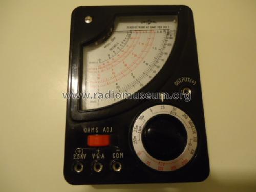
            The middle range ones I used were NOT compensated for that use, and there was a specific input designed to measure Audio (AC) superimposed with strong DC, be it a tube plate or cathode or a transistor collector, no split supply Op Amps way back then either which usually have zero or a few mV DC at the output; such special input was often labelled "Output" to utter confuse Noobs who expected something to come out of it, while true meaning was: "jack to measure Audio Output" of a gain stage.

            And what it did was to add a typically .1uF 400V cap in series with the "regular" AC measuring terminal.

            My beloved Central 200H, most popular cheap multimeter in 1969, on many counts suoperior to current cheap multimeters (and a few mid range ones:

            1) notice the prominent "Output" terminal, which allows it to read AC mixed with strong DC:


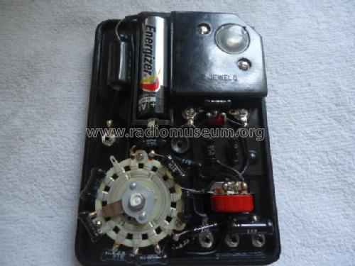
            and the reason why it can: a large mean black .1uF x 400V cap:


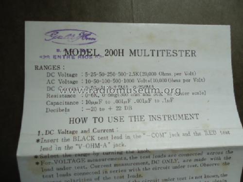
            2) notice it proudly states it can measure Capacitance, right on the Spec sheet:

            2 wide scales: 10uuF (10pF in oldspeak) to .001uF and .001uF to 1uF ... what else can you find inside a (1969) Radio, TV or Amplifier?

            But ... but ... what about electrolytics?
            Electrolytics? (twist your nose as if you were smelling dog shit) ... who wants to measure those?
            "Everybody" knows they are -50% +100% rated, all you want to know is whether they are open or not.

            3) the icing on the cake: it can measure, straight from factory and without any extra test probe, up to 2500V DC

            Definitely no Lawyers writing that user manual or designing front panel.
            Juan Manuel Fahey

            Comment


            • #21
              My Fluke measures up to 5uf I think. I've used it to check larger electrolytic cap values by placing a 4.7uf cap in series with the test and then doing some math. A little off topic for the actual requirements, but it's a good cheat in a similar vein so I thought to include it.
              Last edited by Chuck H; 12-02-2017, 08:27 PM.
              "Take two placebos, works twice as well." Enzo

              "Now get off my lawn with your silicooties and boom-chucka speakers and computers masquerading as amplifiers" Justin Thomas

              "If you're not interested in opinions and the experience of others, why even start a thread?
              You can't just expect consent." Helmholtz

              Comment


              • #22
                Not to take us further away but...

                Are we discussing two things? One could feed a signal through a cap and calculate capacitance from it. I was thinking of meters that could measure capacitance by themselves. I don't recall any meters that spit AC out of themselves into a test cap. Yes the technique using an external signal genny with your meter has been around a long time. But the meter doesn't do it on its own.
                Education is what you're left with after you have forgotten what you have learned.

                Comment


                • #23
                  Originally posted by Mick Bailey View Post
                  Otherwise, as far as cap values go, unless the value has particular significance I leave it alone.
                  Mick, can you expound a bit on that? How would I determine which caps have particular significance and which don't? I imagine it's down to experience and knowledge for the most part, but I'd like to be set on the path toward said experience and knowledge

                  Comment


                  • #24
                    I'm not Mick, and he may have other thoughts on the matter, but...

                    In general, something like a filter cap might have a nominal value of 20uf. In the old classic days of Fender, it was common for filter caps to have a tolerance of -20%/+80%. That means the thing could measure anywhere from 16uf to 36uf and be good and within spec. The value is not critical in a filter cap. Today caps have a much tighter tolerance, but the fact remains it isn't critical.

                    Cathode bypass caps are a close second in many cases. That 25uf cathode cap goes down to way below guitar freqs, so if it measures 20uf instead of 25uf, who cares.

                    In the tone stack, the vales are chosen for the frequencies they represent. If you change them much, then your EQ bands will shift around (I mean more than they already do normally). So they are much more significant.

                    Something like a bright switch is also more significant. If you wander far off the 100pf that is in the specs, it affects how much "brightness" is applied, subtle sparkle ir shrieking shrill. Same with coupling caps between stages, they affect the highs and lows coming through - the tone.

                    Hard and fast rules? No, but those are general tendencies. And it is unlikely a 100pf ceramic cap will measure 300pf or 40pf anyway. Same with film caps. That 0.022uf isn't probably going to be way off. It might get real leaky or short, but that is a different matter.
                    Education is what you're left with after you have forgotten what you have learned.

                    Comment


                    • #25
                      Originally posted by Enzo View Post

                      In general, something like a filter cap might have a nominal value of 20uf. In the old classic days of Fender, it was common for filter caps to have a tolerance of -20%/+80%. That means the thing could measure anywhere from 16uf to 36uf and be good and within spec. The value is not critical in a filter cap. Today caps have a much tighter tolerance, but the fact remains it isn't critical.
                      I have no reason to doubt this but I am curious why different values are used then. For example, a Fender Blues Deluxe uses three 22uF caps along with a (presumably more expensive) 47uF for the B+. So obviously there is a difference in the characteristics or capability of the two values, even if that difference is non-critical. What would the difference be? And then you have other amps with filter cap values of 2200uF (SS only?) for example.

                      Comment


                      • #26
                        We have to decide what we are doing, what is our context. Are we designing an amp, or are we troubleshooting a defective one. VERY different goals. If you design an amp, you decide to put a 12AX7 in the first socket. If I ask you to pull that tube during repair, it isn;t because that will heal or improve the amp, it is to expose the source of the problem.

                        They use different cap values in design to achieve some purpose. But if you are trying to fix it, then we have other priorities. If your amp makes no sound, it doesn't much matter if the filter cap is 10-20-40uf, it will make sound either way. If I am designing, then a larger cap might mean tighter bass response or whatever.


                        As to solid state, tube amps use high voltage and low currents, which at the very end are TRANSFORMED to low voltage high current for the speaker via the output transformer. Solid state amps use low voltage and high current throughout, so much more current is drawn from the filter caps, thus they must be much larger. The SS amp would function with little 20uf caps, but it would be hummy and have lots of distortion on peaks, etc.
                        Education is what you're left with after you have forgotten what you have learned.

                        Comment


                        • #27
                          I'll let others comment on the cap values, just wanted to let you know that aside from power tube type, Symphonic MA50 schematic should be close.
                          Originally posted by Enzo
                          I have a sign in my shop that says, "Never think up reasons not to check something."


                          Comment


                          • #28
                            Originally posted by Enzo View Post

                            They use different cap values in design to achieve some purpose. But if you are trying to fix it, then we have other priorities. If your amp makes no sound, it doesn't much matter if the filter cap is 10-20-40uf, it will make sound either way. If I am designing, then a larger cap might mean tighter bass response or whatever.
                            Right, so this is what was nagging me about the idea of leaving caps alone even if they are significantly off original value. Even in repair mode I may be inclined to be equally concerned with tighter or looser bass response (or some other characteristic) as the original designer was. I guess it comes down to the phrase "non-critical". If you just want it to work with a minimum of cost and effort then "don't sweat the small stuff" , to use a fairly hackneyed expression.

                            Comment


                            • #29
                              Originally posted by bobloblaws View Post
                              Right, so this is what was nagging me about the idea of leaving caps alone even if they are significantly off original value. Even in repair mode I may be inclined to be equally concerned with tighter or looser bass response (or some other characteristic) as the original designer was. I guess it comes down to the phrase "non-critical". If you just want it to work with a minimum of cost and effort then "don't sweat the small stuff" , to use a fairly hackneyed expression.
                              Any change you make will change the way the amp sounds, for better or worse. Putting 'design spec' caps into the power supply with brand-new-cap ESR values, will make it sound different than what the user has come to expect. The human mind has the ability to filter out the hiss and pops to imagine the pristine sound of the amp without the defects. But those same defects are changing the operation of the amp in ways other than the obvious. Maybe the owner has grown fond of the flabby bass they get, and when the replacement design-spec caps tighten up the bass, the owner is disappointed with the result (for example).
                              Not to ignore that once the caps start to fail and drift, you will never know what the actual original value was within the -20/+80% spec range. All the repair tech can do is fix what's broken. The next step after it's fixed - for some people - is to put on the designer's hat and try to recreate with the owner what mojo the equipment may have had, failed caps and all.
                              If it still won't get loud enough, it's probably broken. - Steve Conner
                              If the thing works, stop fixing it. - Enzo
                              We need more chaos in music, in art... I'm here to make it. - Justin Thomas
                              MANY things in human experience can be easily differentiated, yet *impossible* to express as a measurement. - Juan Fahey

                              Comment


                              • #30
                                If you want to blueprint the amp, fine, but don't do it in the middle of the repair process. Like if you were in the hospital for a heart bypass, you wouldn't expect them to do liposuction "as long as they were already in there."

                                But as Escher points out, new caps at specific values will sound different from the older caps regardless.

                                My underlying point was don't get caught up in total overhaul of an amp when you are trying to figure out why it doesn't work. Don't be concerned how tight the bass is until we HAVE bass to tighten.
                                Education is what you're left with after you have forgotten what you have learned.

                                Comment

                                Working...
                                X