Ad Widget

Collapse

Announcement

Collapse
No announcement yet.

Fender Dual Showman....made in 1966

Collapse
X
 
  • Filter
  • Time
  • Show
Clear All
new posts

  • #16
    Originally posted by bsco View Post
    Thanks SoulFetish.....I'll double check that acc outlet.....I do not think that ground is going to come loose.....as I have coated the threads after securing the ground connection....but I might take it off and just solder the wire right to the chassis like Leo had suggested below your post as I have just picked up a Weller 240W soldering gun....that should have plenty of heat for that job.....
    Cheers
    I will often solder the earth wire to chassis in Vintage Fenders in the same way as Leo describes as well. I'm not sure how much contact area the Weller gun can get on the chassis, but 240W should be plenty of heat. I find that going over the area you're planning to soldering with a cheap emery board (or scoring up the chassis with a tool), and using liquid flux really help getting a nice strong solder connection.

    edit:
    Originally posted by bsco View Post
    I sure will.......Can't see why it would not work.........I'll give the chassis a very good scraping and cleaning first.....
    Cheers
    I just read down and saw this. Looks like you are a step ahead of me. Good luck
    If I have a 50% chance of guessing the right answer, I guess wrong 80% of the time.

    Comment


    • #17
      Originally posted by 52 Bill View Post
      The original screen resistors on these amps were carbon comp, 470 ohm, 1 watt. They can get warm and can burn open when a power tube fails. Some people believe that they are used as a fuse and should not be replaced with a higher wattage.
      Think I will switch them back to the 1W and will use FP resistors......

      Comment


      • #18
        Originally posted by SoulFetish View Post
        I will often solder the earth wire to chassis in Vintage Fenders in the same way as Leo describes as well. I'm not sure how much contact area the Weller gun can get on the chassis, but 240W should be plenty of heat. I find that going over the area you're planning to soldering with a cheap emery board (or scoring up the chassis with a tool), and using liquid flux really help getting a nice strong solder connection.

        edit:

        I just read down and saw this. Looks like you are a step ahead of me. Good luck
        Yes sir. That 240W weller monster worked great......

        Comment


        • #19
          Originally posted by Randall View Post
          Let us know if that weller gun does the job.
          Yes sir...That worked excellent....

          Comment


          • #20
            Originally posted by SoulFetish View Post
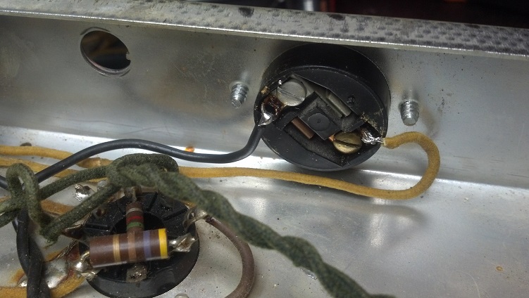
            Here are a couple of important safety points I would make. First, I've often seen the accessory outlet wired incorrectly in vintage Fenders. If you wish to connect the mains live/neutral wires to the accessory outlet, the Live (black) wire MUST be connected to the internal Brass terminal and the neutral to the standard tinned color terminal. These outlets are often polarized two prong AC outlets, and the incorrect polarity could lead to a hazard for people and equipment without the protection of an earthed outlet. This is a matter of electrical code and needs to be wired correctly regardless of the original wiring. Some technicians elect to remove all connections to the accessory outlet, and disengage the receptacle altogether.

            Second, a transformer lug is probably the worst place to make the earth bond connection. Transformers (EI lamination transformers in particular) vibrate mechanically when subjected to an intense magnetic. This is called magnetostriction. The vibration can (and does) cause the nuts to loosen, causing the earth/chassis bond to open. I've seen this on several occasions.
            The earth wire should have it's own designated terminal connection and dedicated fasteners.
            I had another look at that accessory socket...it is polarized......correct me if I am wrong but isn't the wider prong used for the neutral return wire....aka white wire, and the live or black wire is connected to the smaller prong?? this socket has the brass screw on the wide connection and the smaller prong has the silver or tin type screw on it.....with that being the case, the black wire is connected to the smaller prong and the white wire is connected to the larger prong.....from the factory........

            Comment


            • #21
              Yes, the wider prong is normally the neutral. This is also the 'identified wire;' on flat zip cord it will be the ribbed or striped wire.

              Comment


              • #22
                I don't think the color of the screw is significant since they had to be removed in order to get the eyelet on and the underpaid, disgruntled employee of the month didn't care which screw went where he/she put them back in. Which wire going to which side is significant, however.

                I pulled an early '70's chassis with a three-pronger and it has the screws in their proper configuration, but the wires are on the wrong sides. The tin screw is on the wide side, but the black wire is connected to it. An interesting thing is that the wires were cut to lengths that would have allowed the proper connections.

                Comment


                • #23
                  Originally posted by bsco View Post
                  I had another look at that accessory socket...it is polarized......correct me if I am wrong but isn't the wider prong used for the neutral return wire....aka white wire, and the live or black wire is connected to the smaller prong?? this socket has the brass screw on the wide connection and the smaller prong has the silver or tin type screw on it.....with that being the case, the black wire is connected to the smaller prong and the white wire is connected to the larger prong.....from the factory........
                  This is what I was talking about. There was something very deceptive about how it looked and which screw terminal actually connects to which blade.
                  Can you do a resistance check with one probe in the actual smaller prong and see which lug & screw it connects to?
                  Originally posted by Enzo
                  I have a sign in my shop that says, "Never think up reasons not to check something."


                  Comment


                  • #24
                    Originally posted by g1 View Post
                    This is what I was talking about. There was something very deceptive about how it looked and which screw terminal actually connects to which blade.
                    Can you do a resistance check with one probe in the actual smaller prong and see which lug & screw it connects to?
                    Yes sir...I'll be downstairs after supper and I will check it out for you and let you know......
                    Cheers

                    Comment


                    • #25
                      Originally posted by Bloomfield View Post
                      Yes, the wider prong is normally the neutral. This is also the 'identified wire;' on flat zip cord it will be the ribbed or striped wire.
                      Check it again it if you follow the brass terminal, It will go to the thinner prong. But it looks like it’s right behind the neutral one. This confused the shit out of me when I first noticed it. But I’ve never seen The socket terminated incorrectly.
                      If I have a 50% chance of guessing the right answer, I guess wrong 80% of the time.

                      Comment


                      • #26
                        Originally posted by 66 Kicks View Post
                        I don't think the color of the screw is significant since they had to be removed in order to get the eyelet on and the underpaid, disgruntled employee of the month didn't care which screw went where he/she put them back in. Which wire going to which side is significant, however.

                        I pulled an early '70's chassis with a three-pronger and it has the screws in their proper configuration, but the wires are on the wrong sides. The tin screw is on the wide side, but the black wire is connected to it. An interesting thing is that the wires were cut to lengths that would have allowed the proper connections.
                        No it doesn’t matter about the screws it’s the actual terminal that’s a significant
                        If I have a 50% chance of guessing the right answer, I guess wrong 80% of the time.

                        Comment


                        • #27
                          Originally posted by SoulFetish View Post
                          Check it again it if you follow the brass terminal, It will go to the thinner prong. But it looks like it’s right behind the neutral one.
                          Aren't the screws offset 45 degrees from the slots so that either one has an equal distance to both slots? Maybe there are different models?

                          Comment


                          • #28
                            Originally posted by 66 Kicks View Post
                            Aren't the screws offset 45 degrees from the slots so that either one has an equal distance to both slots? Maybe there are different models?
                            I apologize, I meant to say beside the neutral one (or "next to" would have probably been clearer). What I mean by that is, The tab you actually solder to is directly adjacent to the opposite input. So, it's incredibly easy to misidentify which connector goes to what terminal. After a little searching, I was able find a clear photo showing this.


                            This photo is well lit and taken from a clear angle. But the practical reality is that those terminals are recessed in the back of the receptacle, and almost always suffering years of oxide build up. This, coupled with the reality of working over the a receptacle (tucked under the lip of the chassis) is what leads to so much confusion for the technician.
                            If I have a 50% chance of guessing the right answer, I guess wrong 80% of the time.

                            Comment


                            • #29
                              I think the best way to do this is to remove the mounting screws so it can be pulled out from the chassis, install the wiring the proper way and then re-install it...That way you will have a very clear view of the rear of the terminals in question, and if the wiring is not long enough to do that, then it is just a matter of installing a couple of pieces of wire that would be long enough to be able to work comfortable...as it stands now with the unit I have, it s wired correctly.....but in the future I might just pull the outlet from the rear of the chassis.....as it is a bit of a pain to work at that while it is installed.....

                              Comment


                              • #30
                                Originally posted by g1 View Post
                                This is what I was talking about. There was something very deceptive about how it looked and which screw terminal actually connects to which blade.
                                Can you do a resistance check with one probe in the actual smaller prong and see which lug & screw it connects to?
                                Just getting back at this.....had to do a few personal things over the last few days and Had to take care of some stuff for my mom as she has been diagnosed with a form of Alzimers....we now have some appointments set up and have to get some forms filled out by the doctors, etc, etc......ANYWAY.......Hey g1...you are right...Me stupid.....well maybe not totally stupid.....That confused the hell out of me...now that I have this figured out and I have removed that death cap, and installed a new 3 prong cord and have soldered the ground directly to the chassis, there are two small yellow colored wires also connected to the accessory plug.....were they also wired wrong at the factory, or was it just the power cord wires.......if it was only the power cord wiring, then I have it done......
                                Cheers

                                Comment

                                Working...
                                X