Ad Widget

Collapse

Announcement

Collapse
No announcement yet.

Dynacord SUB 600A__thermo part

Collapse
X
 
  • Filter
  • Time
  • Show
Clear All
new posts

  • Dynacord SUB 600A__thermo part

    Hi,

    Need some help - got Dynacord SUB600A full disassembled (fortunately - modules only

    Have plan to "put it all together", but I always like to check all what's possibile (bad idea ?

    Stopped at the "first step" - on the heathsink is mounted some "strange" part, ok
    it's somewhat thermal stuff/protect, but (for me) it becomes strange when I tested it with my
    (trustworthy) Fluke 87 V - reading is "open circuit" ( couple times checked !)

    Can anyone help me with schematic ( "googled" Dynacord SUB600A more than couple times - no luck) or with
    any experience with this (similar ?) part.
    thanks

    Greetings from Croatia

  • #2
    Yes, of course, let me see it.
    Nope, turn it around.
    Nnnnoooooo , under the light ..... there!


    .
    .
    .
    .
    .
    sorry, I guess weīll need some pictures


    Oh, and welcome to the Forum
    Juan Manuel Fahey

    Comment


    • #3
      Thanks for (quick) reply and nice words : )

      (I made photo, but have trouble with "insert" here - need URL ??)

      Anyway, this "strange" part" looks like short black pencil ( approx. 5 cm long) screwed on the heathsink in some alu "holder"

      Last edited by tube_amp; 02-11-2019, 01:18 PM.

      Comment


      • #4
        Of course (NOT) " For your eyes - only ! " )

        Comment


        • #5
          Ok, itīs definitely some kind of thermal sensor or switch.
          Never before saw one like that.


          Whatīs on 95% of amplifier heatsinks is this:


          it has a bimetallic disk inside which "snaps" when heated and either open or closes a circuit.

          Most common is "normally closed" (when cold) and above certain temperature it opens .
          Usually opens mains voltage and amplifier self turns off when too hot, the important thing is that on cooling it self turns on again.
          A few just disconnect the speaker, until amp cools off.

          Some switches are "normally open" and above certain temperature close and turn on a cooling fan.

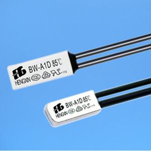
          There is a smaller cheaper version without mounting lugs which is usually pressed against the heat sink with some kind of clamp or put inside a transformer winding, again is self resetting:


          Then there is a completely different component, a thermal *fuse* .
          It has inside a special metal which melts under very low temperature (for a metal that is) , and opens "forever".


          Based on shape and it having axial terminals I suspect you have a thermal fuse, mounted inside an aluminum tube so it can be attached to a heat sink.

          It *can* be replaced but then we must know why it triggered and blew open; manufacturers use them as a "last resort" solution, when they think the amp is very damaged and just want to turn it off, forever, simply to avoid it burning the house.

          So you must investigate a little and post results:

          1) itīs plugged into the other board , you must check what itīs switching: mains voltage? some supply voltage to other areas? a speaker out? follow the tracks from its connector.

          It is just by a large diode rectifier bridge, so it might control what goes into/out of it.

          2) you might try disassembling the "pencil" and sliding actual switch out to read is markings.

          3) IF itīs epoxied in and impossible to remove, you might heat mystery pencil with a heat gun and check whether it switches ON at some temperature.

          Typical reversible switch temperatures are around 85C ; typical unreversible fuse ones are 100C and above, so if tube becomes that hot and nothing happens (itīs still open) then itīs confirmed itīs the irreversible type.
          In that case you can replace it, or even, just for testing, bypass it ..... but then I expect to have some important damage either in amplifier or supply.

          I see the bridge rectifier has 2 unconnected terminals.

          Check what it feeds: a standard amplifier supply, relatively low voltage?

          Or a mains SMPS offline supply?

          Follow tracks and post what value capacitors it feeds: capacitance and voltage.

          Also what feeds it: mains or transformer voltage?

          Post a picture of all modules you have, plus power transformer (if any) so we have a rough idea of what you have.

          Since it uses TO3 case power transistors itīs somewhat dated , maybe 80īs or 90īs , and *could* have a conventional supply fed from a large toroid transformer.

          Looks contemporary because ... well .... itīs "Cherman" , and we know Teutons are always very advanced

          So do your homework and post results.

          Specially show transistors so we can read their codes, I can only see a "J" letter which makes me think they may be Japanese Mosfets ; code might typically be 2SJ**** but the 2S prefix is usually omitted.

          If so, it confirms my guess: in the 80īs **everybody** was using Audio MosFets in their premium stuff.
          Juan Manuel Fahey

          Comment


          • #6
            In short...... (photos "only"


            And the "best"...


            At this moment, it's (almost) "everything clear"... traced this part of circuit, but I can not "imagine", where is (temperature) "point", because I tested
            few days before this "cigar" with heater - no results.

            Comment


            • #7
              It was good actually tracing the circuit

              The circuit shown is a relay trigger, check what does it connect/disconnect, might be mains, might be some internal supply, a fan or even the speaker out.

              The mystery part is the sensor.

              I would expect a Thermistor there, either an NTC which lowers resistance with rising temperature in which case it would turn transistor (and Relay) OFF when hot; a string of diodes, which would do the same, or a PTC where vresistance rises when hot, letting transistor turn ON and activating the relay.

              My doubt is that either an NTC or a PTC resistance, given other values in the schematic, should show a measurable resistance, in the area of, say, 5 to 50 kilo ohms ... yet it measures open.

              Now a string of diodes epoxied inside that metal tube would measure open backwards, and still "open" in the forward direction with standard multimeters, because they apply very low voltage to probes on resistance measurements *precisely* not to turn bipolar junctions ON .

              DIODE setting applies slightly above 1V which is enough to turn on *one* diode junction, barely 2 of them in some multimeters and not at all if you have 3 or more diodes in series so it still rests as a possibility.

              FWIW since bimetallic sensors are somewhat unavailable here and relatively expensive if found, and NTC thermistors went the way of the dodo bird, and being cheap ass myself, I designed and use a single diode sensor which turns fan on at 50C and mutes amp at 90C , both temperatures being fully adjustable ... so I guess that Dynacord circuit may do something similar.

              I suggest you test "cigar" both ways in the Diode setting and as a last resort, feed , say, 15V DC into it, through 10/15k and a LED, both ways.
              If Led lights , even slightly, we confirm diodes in series.
              If so, measure voltage drop across it, each 0.7V means 1 diode in series inside.
              Juan Manuel Fahey

              Comment


              • #8
                Hi Juan,

                My fault (sorry), yesterday I was "in hurry" and forgot to wrote, this relay is - "speaker relay" !

                From my "point of view", this (small) circuit is (speaker : ) relay "disable", and ( think)
                extra added with some "reason" ("Cherman" way of thinkin' ... ? ) at the "top" of "speaker relay"
                circuit.

                Anyway, I'll "take a look" to the rest of circuit (at the another PCB ) via (shown) "socket"

                cheers

                P.S.
                I'll make "LED test"...

                Comment


                • #9
                  Some news...

                  I made "LED test", and "no light is there" (with voltage sweep from 5v to 35v )

                  Mistery remains the same, from beginning - "black cigar" temperature characteristic !
                  (any suggestion for some replacement ? - I have "some experience", but with temperature components -NOT so much : )

                  And few photos of the "THING" ( for the big picture : )
                  Modules are placed,but NOT finished - input board is above output "cage" ( heathsink & "black cigar" )

                  regards


                  Comment


                  • #10
                    Excellent.
                    At least now we have a better idea, specially that it has a conventional (toroid) power supply, how itīs fan cooled, etc.
                    Is that the original chassis?

                    If not, it fits the modules incredibly well, specially cooling slots and connector holes.

                    As of the thermally controlled relay, I would worry not too much about it.

                    I *hope* the speaker out is enabled by default, and itīs interrupted only when mystery sensor detects a too hot temperature.
                    In that case the 100k/6k8 string should turn BC327 ON, enabling the relay; thermal sensor should be open or high resistance (so far itīs open) and lower resistance or short when hot, so shorting BC327 base to emitter, turning it OFF and opening the relay contacts.

                    Sensor *might* even have some bimetallic strip or "spring" inside, normally open, which expands or twists when hot, closing a circuit and shorting transistor BE

                    My point is that amp probably works without this safety circuit, so try to have it working first and then worry about protection and such.

                    **Absolute** worst case, that amp does not work and you canīt find the problem because of lack of schematic, coupled to a complex circuit, remember the main and most expensive elements are the power transformer (and large power supply components) and those expensive and almost impossible to find lateral MosFets.
                    What I would do here in Argentina: I would (remember, absolute worst case) junk most of the circuit, and build a "datasheet suggested" Hitachi Mosfet power amp PCB (look at the HH VS500/800 or Trace Elliot power amps for "inspiration") which is frighteningly simple, to drive the MosFets, fed from existing supply, and call it a day.

                    You can build a small Fan supply and add a generic, relay activated DC speaker protection and you will end with a functional equivalent to what you have there today. (you feed signal to it and drive speakers)

                    You already have the most expensive parts; the rest "can be" simple if the original one is tough to solve.
                    Just use *always* a lampbulb limiter and take care of your expensive MosFets.

                    Click image for larger version

Name:	300W MosFet amp + supply.jpg
Views:	1
Size:	103.6 KB
ID:	853053
                    Juan Manuel Fahey

                    Comment


                    • #11
                      In "one word" - I agree with you !

                      My conclusion was "exacty" the same, at the moment when I traced/draw those part of circuit.

                      Back to the AMP !! : )

                      Chasis is original, and it is the part of mentioned Dynacord product - SUB600A ( active subwoofer )
                      This amp drives (lovely ElectroVoice speaker EVX-180 (you was right - it's premium stuff , produced, I suppose in mid 90'

                      This weekend I planed to test whole amp, "step by step",with some precautions (current limit and dummy load), and YES - with
                      same idea to do not worry too much about "black cigar SYS" (as I told before, it's "only" to disable speaker at some overheatings )

                      Comment


                      • #12
                        Hi

                        With (some ? delay, I have "lack of time" like some kind - constant....

                        Ok, back to work... I powered up the amp and got couple (very interesting) conclusions and questions.
                        First, and most important - the amp works !!!

                        Now (still without the schematic) questions becomes more "sophisticated".....
                        As shown at the photos, the amp drives 8 ohm load with 100 Vpp, and it "can do that - endless".

                        [IMG][/IMG]

                        ( note: power supply have +/- 90 Vdc for Mosfet output )

                        After (small ) research with input signal I concluded that some kind a "compressor" is activated.
                        With increasing input signal, output voltage reach 160 Vpp, and after few seconds the output
                        voltage decreases to mentioned 100 Vpp.


                        With some tracing I found the "culprit", that's small piggyback board..... to be honest, it works without any objection, with any signal degradation....

                        At this moment, may be best idea is - "leave it" and use it with this settings.
                        Any suggestion (or idea is welcomed !

                        cheers

                        Comment


                        • #13
                          In principle, leave it.
                          Even if only because "Dynacord are no fools" and "they" put it there.

                          Digging a little deeper:

                          * you have +/- 90V rails , either no load (or no drive) or into 8 ohm, but:

                          * even although you have a massive transformer, all power supplies drop under load.
                          Even more under heavy load, so you will not only have less than +/-90V available, but also remember that Mosfets in general (and Laterals even more) have higher saturation voltage loss than equivalent Bipolars.

                          Not talking Vds(sat) here which can be quite low but Vgs needed to make them pass high current. We can easily loe 6 to 8V peak there.

                          Also residual resistance is quite high in Laterals, thatīs why for switching duty Verticals are preferred.

                          * 100Vpp limiter setting means slightly over 35V RMS which nicely matches 600W RMS into 2 ohm load, so they may very well have preset that value knowing itīs realistic.

                          Wouldnīt be surprised at all about Dynacord having a custom ordered 2 ohm voice coil heavy woofer.
                          After all, JBL EON speakers use 2 ohm coils too, and certain versions go down to 1 ohm ... or 2 2 ohm coils in parallel .

                          If you will use it only with an 8 ohm speaker *maybe* you could disable the limiter, in which case you could get (160/2.83)^2 /8=400W RMS ... but then it will be free to distort if fed a large signal and you might fry your speaker.

                          Your choice
                          Juan Manuel Fahey

                          Comment


                          • #14
                            Hi Juan

                            First, I would like to say the great THANKS to you , for big help (and motivation )
                            Personally, I became (a "little bit" : ) "lazy", and your approach really suited to me during
                            this "adventure".

                            In last mail you made GREAT math with 600w "conclusion", and especially about Mosfet's "nature"
                            (during my over 30 years overall experience I never "faced" with them )

                            Also,your English is (MUCH) better then mine, For "four sentences" I have to spend "four hours" to write
                            That was a main "reason" for my "incomplete" observations.

                            Again, thanks a LOT !

                            best regards

                            P.S.
                            "The Black Cigar Mystery" remains, but I hope that will never be (accidentally : ) "discovered"
                            Last edited by tube_amp; 03-12-2019, 09:58 PM.

                            Comment


                            • #15
                              Thanks
                              Please fill your Country/Location data in your member page, it always helps getting better suggestions.
                              Juan Manuel Fahey

                              Comment

                              Working...
                              X