 Tweet
Tweet
Here is something which may be of some interest, and some of you may have experienced as well.
We received an old 6G6 Fender Bassman that came in for service. It had been modified a bit, but the customer opted to have the amp restored to the original circuit.
Here is the Schematic:


The filter and bypass caps needed replacement, rewired for original GZ34 rectifier, new tubes were installed, and some coupling caps needed replacement.
Easy enough. However, when I went to sine wave check the amp under load, I noticed some strange behavior at the output. Here is a clip of what would happen as I brought up the signal level:
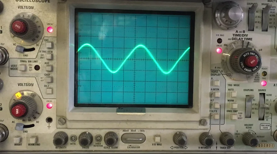
https://vimeo.com/332879913
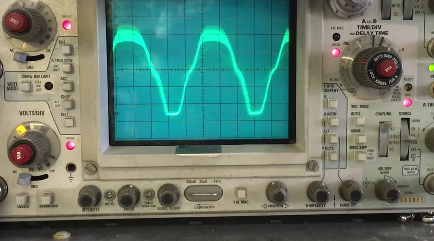
When I brought the signal level up (inserting signal into the normal channel), I noticed the sine wave collapse in an unbalanced way. It almost looked as if the power supply was collapsing, but would then stabilize. I've seen rectifier tubes at the end of life exhibit something like this, but they generally don't recover after. Plus, I quickly eliminated the recti as the issue.
I then suspected either one of the new filter caps might be faulty, or coupling caps. I thought output had a look as though there was an instability in the charging/discharging of one or more coupling caps though.
The power supply tested stable. We did trace the problem to the PI stage, specifically to the mixing stage at the input of the PI. When I lifted the 470k mixing resistor coupling the bass channel, the issue went away. More specifically, the problem seemed to be centered around the .1�F coupling cap before the Treble control in the bass channel when the 2 channels are connected, as only when this cap was connected did this issue exhibit.
I thought that there was some kind of feedback occurring between the two channels, and thought that more channel isolation might solve the problem. So I increased the 470k mixing resistors to 820k, but this did not solve the problem. Interestingly, I could not audibly hear what we are seeing on the scope when driving the amp using a guitar through the input of the normal channel.
The one thing that did seem to mitigate this was including another capacitor after the 470k resistors and before the grid (as is included in the 6G6-B version). The value needed to be kept under around .047�F in order to keep the amp from exhibiting the behavior, but it did appear to attenuate the signal level a little.
I was wondering if any of you have seen this, and what you have done?
We received an old 6G6 Fender Bassman that came in for service. It had been modified a bit, but the customer opted to have the amp restored to the original circuit.
Here is the Schematic:
The filter and bypass caps needed replacement, rewired for original GZ34 rectifier, new tubes were installed, and some coupling caps needed replacement.
Easy enough. However, when I went to sine wave check the amp under load, I noticed some strange behavior at the output. Here is a clip of what would happen as I brought up the signal level:
https://vimeo.com/332879913
When I brought the signal level up (inserting signal into the normal channel), I noticed the sine wave collapse in an unbalanced way. It almost looked as if the power supply was collapsing, but would then stabilize. I've seen rectifier tubes at the end of life exhibit something like this, but they generally don't recover after. Plus, I quickly eliminated the recti as the issue.
I then suspected either one of the new filter caps might be faulty, or coupling caps. I thought output had a look as though there was an instability in the charging/discharging of one or more coupling caps though.
The power supply tested stable. We did trace the problem to the PI stage, specifically to the mixing stage at the input of the PI. When I lifted the 470k mixing resistor coupling the bass channel, the issue went away. More specifically, the problem seemed to be centered around the .1�F coupling cap before the Treble control in the bass channel when the 2 channels are connected, as only when this cap was connected did this issue exhibit.
I thought that there was some kind of feedback occurring between the two channels, and thought that more channel isolation might solve the problem. So I increased the 470k mixing resistors to 820k, but this did not solve the problem. Interestingly, I could not audibly hear what we are seeing on the scope when driving the amp using a guitar through the input of the normal channel.
The one thing that did seem to mitigate this was including another capacitor after the 470k resistors and before the grid (as is included in the 6G6-B version). The value needed to be kept under around .047�F in order to keep the amp from exhibiting the behavior, but it did appear to attenuate the signal level a little.
I was wondering if any of you have seen this, and what you have done?

Comment