Hi everyone,
i built this on breadboard, it runs from +12 and -12 volts.
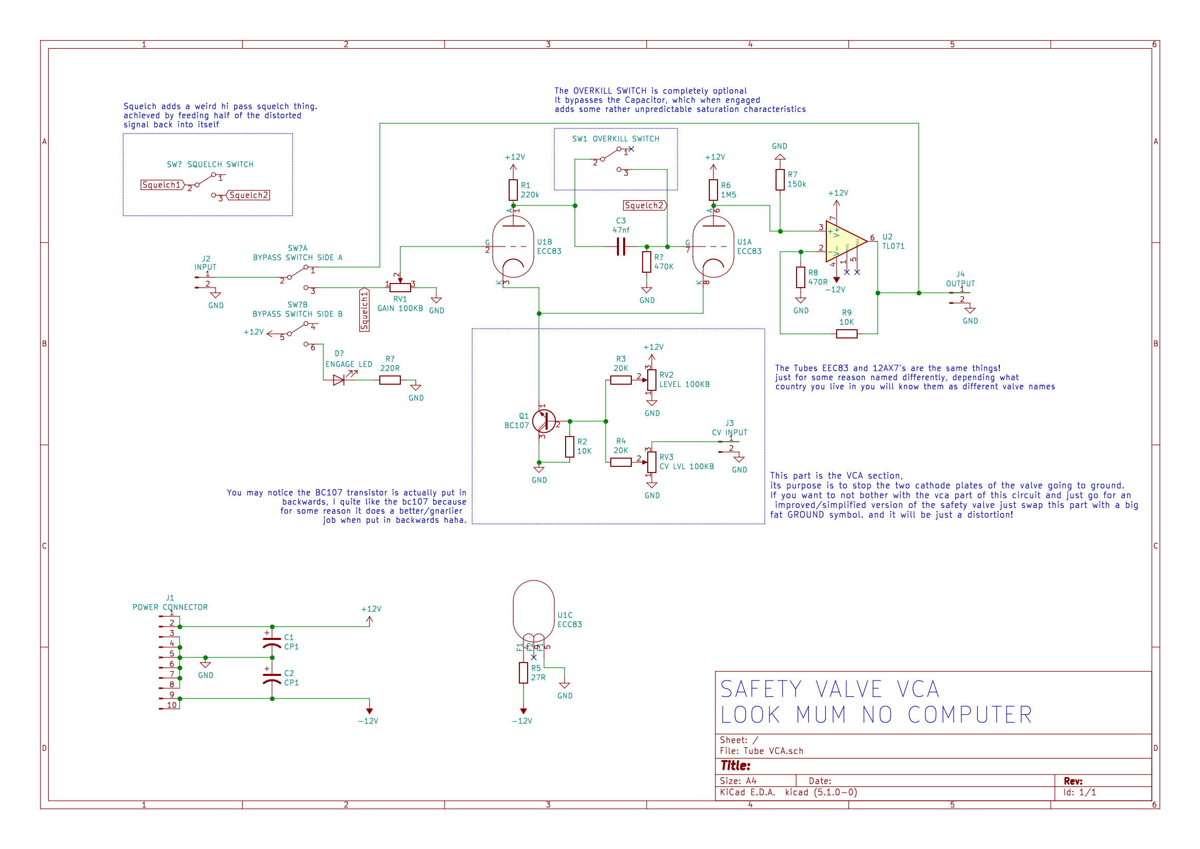
Circuit works, besides the error of pin4 and 5 inverted in the schematic layout compared to the veroboard layout(which is good) the rest looks right but i can't make it work by myself on my breadboard.
I built it 3 times already, same issue each time.
I can visualise on the oscilloscope the waveform entering pin 2 and going out of pin 1 and then into pin 7 but i have no signal at all just a 1.2v steady dc fixed voltage at pin 6, no waveform, same thing at the opamp input at the right on the schematic.
Any ideas what can happen?
I verified everything so many times already, the tube filament heats up, i have an oscilloscope and multimeter i can test what ever you suggest.
Forget about the switches for the moment that are on the schematic i dont wire them up just to keep it simple.
But one time i tried to add the bypass switch shown at the left and while the breadboard not powered i could see the waveform that i put at the input socket going into the power suply, i mean by that its a eurorack power suply and there is leds for +12 -12 and +5v that show when its active but they were lightning on even if i disconnected the psu from the power source, the sine wave form at the input was going back into the psu bussboard, if that can even give a hint...
The vca part in the blue dotted square at the bottom was working fine i could see the waveform being modulated from the control voltage input that i feed it.
It's really just that the signal doesnt come out of the pin6 of the tube.
Thanks a lot here's the info about the circuit:
https://www.lookmumnocomputer.com/pr...distorting-vca

 late gets meager 12V through 220k resistor, grid is at ground voltage, cathode gets some current through reverse biased Q1, and amplifies.


Comment