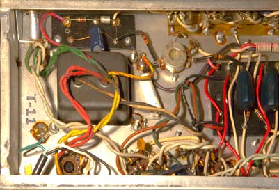
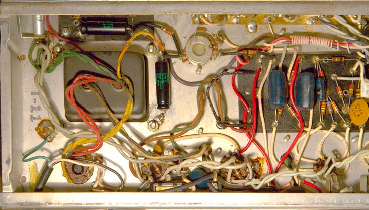
The fault goes further back than the socket. I would change the 50/70 caps first, then the pot if that doesn't work. 100uF/100v axial caps are widely available and do the job well. I truth I'd probably just renew everything in the bias circuit to make sure - the 50/70 caps, the 1k, the diode, the 15K on the pot, the pot, the 2 x 100k - can't be too careful with bias.
Ad Widget
Collapse
Announcement
Collapse
No announcement yet.
Vibrolux Reverb Bias?
Collapse
X
-
Thanks,
At the risk of expecting too much:
Is it reasonable to think that a problem so far "up stream" would cause varying effects out at the tubes?
In other words it confuses me that both tubes are not similarly impacted by a problem that might be shared.
Not trying to argue... just a sincere student type question?
best regards,
mike
Comment
-
Yes, problems way back in the bias supply will certainly affect the bias at the tubes.
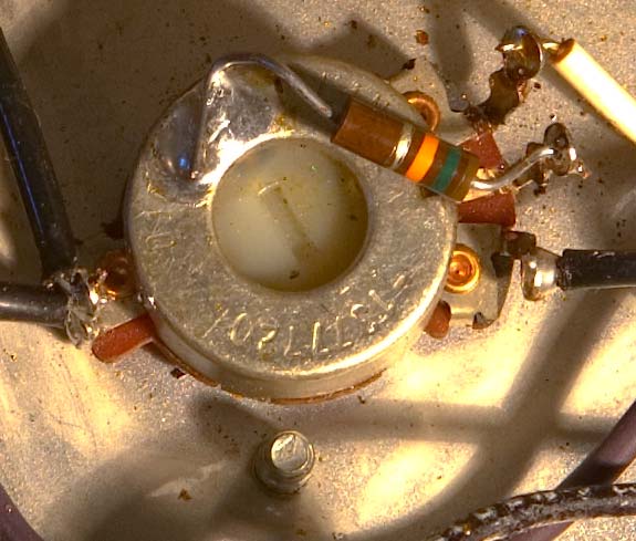
That pot is the famous silverface bias balance pot. Many people like to rewire these for a blackface bias adjust control, but I like them because you can use them to balance any old pair of tubes and dial out hum. You can adjust the bias level if you want to by changing the 15K resistor soldered to the pot.
Anyhow, the fact that one side is affected more than another is possibly traceable back to the pot, which actually distributes and adjusts the bias voltage between the two sides. Pots are mechanical in part and so prone to failure. Some problem with one side of the track maybe.
But because the problem seems to go back beyond the pot I'm thinking that maybe one of the caps is at fault. The mere fact that the bias pot presents different resistances between the supply and either side of the power amp could be responsible for the imbalance you're observing - in a bias circuit small resistance changes can have large effects on voltage.
So it's not as obvious as it at first seems (and as it at first did to me!) that the pot is at fault. Anyhow, bias voltage supply is crucial, and the parts involved are few and cheap, so I'd always think of replacing the lot.
Comment
-
Unplug the amp and pull out the power tubes.Originally posted by mike_mccue View PostThanks,
At the risk of expecting too much:
Is it reasonable to think that a problem so far "up stream" would cause varying effects out at the tubes?
In other words it confuses me that both tubes are not similarly impacted by a problem that might be shared.
Not trying to argue... just a sincere student type question?
best regards,
mike
Replace both bias supply filter caps...make sure the positive end is grounded.
Spray some of your pot cleaner in the bias balancing pot and swish the control wiper around full rotation left and right a bunch of times and then set the voltage on the power tube socket's, lugs 5, so that there is the same negative voltage on each lug with no tubes installed.
If you are able to do that and you are SURE your power tubes are OK, then the sockets are bad and need cleaning and retensioning or, replacement.
Comment
-
Yes, wedge the sharp object between the socket pin and the side of its hole to shove it inwards. I sometims use a jewelers screwdriver. I have a pointy tool sorta like the dentist uses I sometimes use. One of those large size safety pins like for diapers also works.
Check this out, I use it all the time. Most any auto parts store should have them.
http://www.sjdiscounttools.com/kdt2554.htmlEducation is what you're left with after you have forgotten what you have learned.
Comment
-
IMHO,Originally posted by Bruce / Mission Amps View PostI find squirting a little Deoxit in the tube socket holes and then pushing the tube in and out, with a pin wipe from a clean rag each time, can drag some junk out.
I'm hesitant at using Deoxit on tube pins, especially power tubes that run base-up. You may very well encounter heat that Deoxit isn't rated for (I don't know that rating for the current product), and turn it to varnish. I flush the socket with a non-residue cleaner, using the tube as you describe to help clean the socket while the stuff dries off, and then use a ProGold GxL pen (older 400 deg. C formula) on the pins.Last edited by Dave Curtis, dB AudioTech; 05-04-2008, 12:27 PM.
Comment
-
Thanks guys,
I installed the 2 100uf 100v negative bias capacitors. I used some Sprague Atoms but I also bought some Xicon hi Temps. I had finished with the Sprague install before learning that Xicons are considered a good swap.
old:

new:

In any event, I tensioned the socket pins as described and recommended.
I powered up without tubes and measured the voltages.
I'm starting to think my meter is getting old... I swapped batteries with a fresh one... but the old turned out to be strong. What I'm noticing is that the meter seems sluggish.
The voltages at the new caps seemed very stable.
The voltage at pin 5 of the socket near the rectifier tube is -61.3vDC and rock solid stable.
The voltage at pin 5 of the socket near the driver tube seems to stabilize after taking a while to increase. That's what makes me question my meter... it seems sluggish, but on this socket more so than on other measurements.
Once I felt like I could measure the stable voltages (albiet I wait for the *problem* socket to stablize each time I measure) I tried to balance them with the adjust pot. I found that I had to twist the pot to it's limit yet the closest to a match that I coul set was -61.3vDC on the good socket and -60.1vDC on the bad socket.
OK,
So I installed the tubes and powered up, made observations, and powered down. I swaped the tube positions and repeated.
The red plating only occurs on the *problem* socket.
I have other 6L6 tubes but hesitate to expose them to the red plate until I sort this out further.
Is the merit of replacing the sockets related to the fact that you're likely to also replace the coupling caps and small resistors?
thanks for any comments you might share,
mike
Comment
-
thanks for taking a close look.
Yes that's 2 resistors in series, a legacy repair/mod I suppose, going from the pot's center tap to ground.
Each resistor seems to measure apprx 8k (Grey, Orange, Green?) but when I measure the series it says 0.6k... so I'm gonna replace that assembly right now with a 15k as spec'd.

The other 2 taps seem to go to the board and the 100kOhm resistors where I'd expect.
After replacing the 15k resistor I was better able to balance the neg bias voltage at pin 5 of either socket at apprx -61.2vDC.
But the what ever tube I place in the socket near the driver tube goes cherry red within a few minutes of power up.
I'm still having difficulty measuring the voltage on the problem socket... it's sluggish. The measurements on the good socket seem stable and I did some B+ tracing and the meter seemed responsive.
Is that a possible clue about where the problem with the circuit to the problem socket may be?
I need to get some 2000pf caps and then I guess I'll replace the two sockets.
In the meantime I'm still eager to hear suggestions.
best regards,
mike
I guess it's time to install new sockets and components?
any suggestions?
Comment
-
Ok the bias supply seems to be ok, but something is still pulling down the grid voltage on the one output tube.Originally posted by mike_mccue View PostAfter replacing the 15k resistor I was better able to balance the neg bias voltage at pin 5 of either socket at apprx -61.2vDC.
Pull out the red-plating tube, and measure the voltage at pin 5. If the -61 volts does not read correctly, turn off the amp and lift the end of the 0.1 PI cap. Turn on the amp and see if the cap is leaking any voltage. If it is replace both the PI caps and check the amp again.
If the PI cap is ok, then try lifting the end of the 2000pF cap at pin 5. Does this fix the voltage here?
Hope this helps.
Comment
-
I'd be looking at removing the ceramic caps on lugs 5.Originally posted by 52 Bill View PostOk the bias supply seems to be ok, but something is still pulling down the grid voltage on the one output tube.
Pull out the red-plating tube, and measure the voltage at pin 5. If the -61 volts does not read correctly, turn off the amp and lift the end of the 0.1 PI cap. Turn on the amp and see if the cap is leaking any voltage. If it is replace both the PI caps and check the amp again.
If the PI cap is ok, then try lifting the end of the 2000pF cap at pin 5. Does this fix the voltage here?
Hope this helps.
Comment
-
Thanks to both of you.
I'll try both things.
Are the ceramic disks on pin5 just the after thought caps put on to squelch squeal that resulted from less careful construction during the mass production runs?
Can you just pull them and see if the amps runs without running away?
best regards,
mike
Comment
-
WOW thanks everyone
Great News,
I pulled both 2000pf supression caps and took measurments. The voltage had dropped a bit to apprx -60.0 but both pin 5 measurments were quick and easy to do. They readings indicated the voltage was solid and stable.
The bias trim seemed to be even more capable of helping set the voltage to be nearly identical at each power tube socket.
The amp sounds great. I've never heard it before... now I can get to the fun of playing it for a while.
I may suggest a cap job for good measure.
I can't express my gratitude for the help adequately, THANKS.
feel free to add any suggestions or tips.
best regards,
mike
Comment
-
Glad to hear the amp is up and running now.
As you had noted earlier, the bias control is really a bias balance control, used by Fender to "match" output tubes. Now would be a good time to actually set the output tube bias based on current draw, to see what the amp can really sound like with a new set of properly biased output tubes.
You had mentioned looking into a bias probe of some kind, did you ever purchase one?
Comment
Comment