Ad Widget

Collapse

Announcement

Collapse
No announcement yet.

Fender Princeton 112 Fuse blown

Collapse
X
 
  • Filter
  • Time
  • Show
Clear All
new posts

  • Fender Princeton 112 Fuse blown

    Hello,

    A friend of mine a month ago started having a problem with this FENDER PRINCETON 112 Plus Guitar Amp (manual link):


    He said he started to hear a background sound, like 'Ammm' ..

    When disassembling the amplifier the wire\piece of the sepaker negative fell (I assume it was not well soldered):
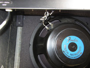


    I just put a screw on the piece that connects to the speaker metal:


    I check the Board and visually it wasn't bad, I just cleaned it with a cleaning spray (Contact cleaner R-10), i plugged it in and i didn't heard any noise, I assumed that the problem was that 'Ground' connection at the speaker..And returned it to my friend.

    He then tested it and the first time it was OK, But the next time he turned it on the background noise appeared again and, coincidentally or not, the 1A fuse blew.

    I have now opened it again but honestly, apart from the fuse, everything seems OK.


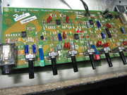
    Bottom of the board:
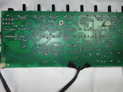


    'Reverb' seems fine, everything makes contact ..


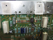
    The Big capacitors are fine:


    The 4 diodes are OK:
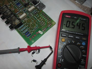
    I tested the CR13, CR14, CR26, CR27 too.

    The Big white resistors seems fine (have approximate values).

    For the two transistors i took them off and i had this readings:

    TIP147 (PNP - BCE)

    C->B: ~ .567
    E->B: ~ .761
    C->E: ~ .441 (Here at the beginning I thought that there shouldn't be any reading but, I presume, that being a Darlington is normal)

    TIP142 (NPN - BCE)

    B->C: ~ .527
    B->E: ~ .648

    E->C: ~ .418 (The same thing I said above ..)


    The speaker is ok, has a resistance of 7R and it works:
    http://youtu.be/KAMlXAuWe8U

    Now, i put everything in place, i soldered all the joints of the board and clean it with isopropyl alcohol.

    I put new thermal paste on the Transistors, should i put more or this is enough? (i didn't took the thermal pads off, just cleaned the superficial old thermal paste and put a new one between transistor and thermal pad.)


    Do you think that i can put a new fuse and plug it in or its better to check something else?

    Thank you
    Last edited by jforum; 06-13-2020, 08:12 PM.

  • #2
    Don't try it out until the problem is addressed or precautions are taken. You face a serious risk of blowing up the speaker and possibly more. It is unlikely that anything you've done will have any impact on the problem. Getting humming sound and fuses blowing indicates an excessive current draw.

    Do you have a bulb limiter? If not make one. I suggest a 60W bulb. If something bad happens it will give you more time to react to save things. Disconnect the speaker to protect it.

    Power up using the bulb limiter and then check for DC volts on the speaker wires. A hundred mV or so is OK. More means you need to check the power rails and power amplifier. If OK try using headphones to listen for the hum. Also tap / flex the board in case there is an intermittent that causes the hum and or high current. We need to get it into the faulty state so we can fix it.
    Experience is something you get, just after you really needed it.

    Comment


    • #3
      Thanks for the answer. I don't have a bulb limiter but I had already thought about doing one, I will look for a 60w or 80w lamp in this case and test it that way.

      Comment


      • #4
        And don't expect bad parts to look different. You cannot tell a bad battery or water pump in your car by looking. A bad transistor looks like a good one. Only exception is catastrophic failures that burn them up. Mostly that does not happen.
        Education is what you're left with after you have forgotten what you have learned.

        Comment


        • #5
          Hello again
          Today i put a new Fuse (1A) and test it with one 60W Bulb lamp, this is the result:

          I connected the multimeter (5.2 mV) on the speaker wires.

          What do you think?

          Comment


          • #6
            So, i test the voltages and... the result:

            I used the multimeter on this GND point:

            And the measurements were:

            Most are AC Voltages..

            Comment


            • #7
              Originally posted by jforum View Post
              Hello,

              I put new thermal paste on the Transistors, should i put more or this is enough? (i didn't took the thermal pads off, just cleaned the superficial old thermal paste and put a new one between transistor and thermal pad.)


              Do you think that i can put a new fuse and plug it in or its better to check something else?

              Thank you
              I suspect what is interpreted as 'superficial old thermal paste' that you cleaned off was in fact part of the insulation of the thermal pads. When you have to pry off the xstrs from the thermal pads, that peels away the part of the insulation system of the greaseless insulator pads. You need to replace the pads with fresh new ones, or use mica insulators and thermal grease. Damaged greaseless insulators being reused no longer have the proper insulation, and can result in shorts between the collectors and the heat sink.
              Logic is an organized way of going wrong with confidence

              Comment


              • #8
                Originally posted by nevetslab View Post

                I suspect what is interpreted as 'superficial old thermal paste' that you cleaned off was in fact part of the insulation of the thermal pads. When you have to pry off the xstrs from the thermal pads, that peels away the part of the insulation system of the greaseless insulator pads. You need to replace the pads with fresh new ones, or use mica insulators and thermal grease. Damaged greaseless insulators being reused no longer have the proper insulation, and can result in shorts between the collectors and the heat sink.
                Really? When i said that i clean the white 'thermal paste' they stayed like this:


                The thermal pads (or Micas) covers all the bottom side of transistor..

                Comment


                • #9
                  What type of thermal paste are you using? To me it looks a lot like arctic silver, but that stuff is conductive. Hopefully it's not that stuff in there. Other point is that when you check voltages with the light bulb limiter connected it will make voltage readings appear lower. Also, for right now you just need to focus on the DC voltages to get the amp stable. TP9-21 are more or less for testing with AC injected into the input of the amp and testing the circuit in that condition.
                  When the going gets weird... The weird turn pro!

                  Comment


                  • #10
                    Originally posted by jforum View Post

                    Really? When i said that i clean the white 'thermal paste' they stayed like this:


                    The thermal pads (or Micas) covers all the bottom side of transistor..
                    OK, my mistake. The white thermal paste sounds like DOW Corning Silicone Thermal Compound, and it looks like that in this latest photo. I thought they might have been the greaseless variety, which can self-destruct in re-use.
                    Logic is an organized way of going wrong with confidence

                    Comment


                    • #11
                      Originally posted by DrGonz78 View Post
                      What type of thermal paste are you using? To me it looks a lot like arctic silver, but that stuff is conductive. Hopefully it's not that stuff in there.
                      I was wondering that too. (last pic in post #1)
                      I don't think I've ever seen grey colour heatsink grease that was non-conductive. Anybody else?

                      Originally posted by Enzo
                      I have a sign in my shop that says, "Never think up reasons not to check something."


                      Comment


                      • #12
                        Yes is artic silver MX-4 and its non-conductive..

                        "he ARCTIC MX-4 is a metal-free and non-electrically conductive compound. That eliminates the risks of short circuit and provides protection to your computer"

                        "The ARCTIC MX-4 is metal-free and non- electrical conductive which eliminates any risks of causing short circuit, adding more protection to the CPU and VGA cards."

                        Do I have to remove it?

                        Comment


                        • #13
                          Well as long as it's not conductive I see no problem leaving it. Are your voltages taken with the light bulb limiter connected? It seems lower in the voltage chart as you mentioned but the those -/+16v rails are right on. I would double check that TP23 where it's supposed to be -16v but you got 0v.

                          edit: btw if the bulb is still connected how does it respond? e.g. Lights up a tiny bit then goes dim. That is what you want to see happen.
                          When the going gets weird... The weird turn pro!

                          Comment


                          • #14
                            Originally posted by DrGonz78 View Post
                            Well as long as it's not conductive I see no problem leaving it. Are your voltages taken with the light bulb limiter connected? It seems lower in the voltage chart as you mentioned but the those -/+16v rails are right on. I would double check that TP23 where it's supposed to be -16v but you got 0v.

                            edit: btw if the bulb is still connected how does it respond? e.g. Lights up a tiny bit then goes dim. That is what you want to see happen.
                            Yes the lamp behaviour is like you said.. lights up a tiny bit then goes dim.
                            I will then remove the lamp from the diagram and turn it on directly to see if the fuse blows or not, if it doesn't blow I see the voltages again.

                            As for testing, I don't have any guitar Can I insert an audio signal from any MP3 player or similar into the INPUT?

                            Comment


                            • #15
                              Originally posted by jforum View Post
                              As for testing, I don't have any guitar Can I insert an audio signal from any MP3 player or similar into the INPUT?
                              That will work great!

                              When the going gets weird... The weird turn pro!

                              Comment

                              Working...
                              X