Announcement

Collapse
No announcement yet.

Fender 3-button footswitch DIY (Roc Pro/Performer 1000)

Collapse
X
 
  • Filter
  • Time
  • Show
Clear All
new posts

  • Fender 3-button footswitch DIY (Roc Pro/Performer 1000)

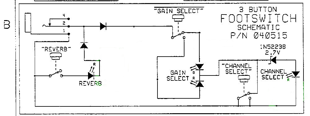
    edit to add: For reference - this has been solved. My successful circuit just used the original circuit included in this post. Worked like a charm. Hopefully the photo server I used doesn't go black in the future, but if it does you can find the footswitch schematic on the full amp schematic for Fender Roc Pro 1000 (same as Performer 1000).
    You can use a simple single red LED (where circled in highlight) because "reverb" and "channel select" are dark when off anyway. Otherwise a three-lead 2-color LED will work for all three as the green leg is just shorted to ground.


    Hi folks.
    I am trying to get a buddy's Roc Pro 1000 amp head working, with some success so far. I found the schematic & parts list, ordered a bunch of stuff from Mouser and did a shotgun replacement of a couple dozen parts (or so). This was my path of least resistance because though I fiddle with electronics a bit, I don't know much really so I'm kinda lost tracing a signal or the like to do actual troubleshooting unless it's fairly basic, i.e. I could trace a signal, but I wouldn't know the diff between what the scope shows vs. what it's supposed to show.

    Originally the clean channel worked but it wouldn't switch to the gain channel even though the LEDs indicated it was. Replaced electrolytics & high-watt resistors just because, FETs and the op-amp chips because I'm actually good at board re-work and have the tools for it, so felt confident. Anyways, after that, the amp is working correctly now, so whatever was the problem seems to have been exorcized.

    Here's my question: buddy doesn't have the foot pedal but I saw that the circuit is shown on the schematic, and it's pretty simple. I figured I could just build one for cheap. However, I see a couple strange things going on for a couple of the indicator LEDs Looks to me that they are basically shorted between the two legs and there's nowhere for the current to flow through them. Is this an error on the schematic or am I just too dumb to know what's going on with them?
    Here's a capture of the section I'm talking about:


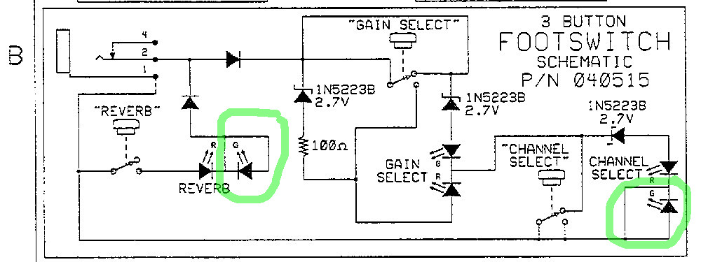
    Isn't the two LEDs I circled just shorting the two legs on the green side and won't light up? Maybe this is supposed to just be a two-color R/G led and it's just supposed to go dark for green? I dunno. I just figured I'd use separate LEDs since I've got them in a bin, but should be the same as a two-color LED. Anyways, maybe I'm just reading it wrong, but it sure appears that it's either got typos or some other magic Kung Fu is going on that I don't understand.

    Anyway, I'd appreciate if somebody took a glance at this schematic and let me know if it looks right in general or totally wrong and won't even work. It would be cool if it worked because I could basically make it for free since I have all the parts in my stash already.
    Thanks for any help - it is definitely appreciated.
    Last edited by Vinito; 01-10-2021, 04:56 AM.

  • #2
    It means on this particular footswitch circuit, they do not need the second color, it is just red on or off.

    The difference in parts cost is trivial, and this way they don't have to stock multiple kinds of LED.


    One thing to be aware of, in this circuit - and I am including the whole switching circuit in the main amp - the voltage drop across the LEDs does matter.
    Education is what you're left with after you have forgotten what you have learned.

    Comment


    • #3
      Here's the trick on a lot of modernish Fender footswitches, at least ones with more than one button. Instead of having multiple conductors like other footswitches they use one conductor and can essentially encode the switches position on it. They have a 40VAC sine wave in the amp which is sent out on the TS footswitch cable. The switches, LEDs, and diodes will clip that 40V sine wave. On a two button switch one will clip the positive part of the sine and the other will do the negative. The amp senses the clipped waveform and can then turn that clipped voltage into a logic level to switch the channel or effects. On a footwitch with more than two buttons the sine wave can be clipped at multiple amplitudes depending on the LED forward bias voltage, the amp then switches the amp based on those voltage levels.

      If you watch Ebay and Reverb you can usually find these pedals for less than $30. To me it is not worth my time to try to make one for that kind of money.

      I love these amps BTW. I have a Roc Pro and a Performer 1000 (same amp, different look) now, and have had three more of them in the past. Tons of power, great cleans, fairly small and light.

      Comment


      • #4
        Well first, thanks for the fast replies!
        glebert - Ahh. I figured something like that was going on inside the amp, being just a 2-conductor plug and all. I had no idea about clipping a sine wave though. You electifical wizards are clever. I was kinda thinking maybe it read a resistor sum or something, but had no idea how that would work without some sort of microcontroller or something. But again, I am not very well-versed in circuit operation so...

        Well I'm going to assume the unmarked diodes near the plug have a pretty standard voltage drop and if I go ahead and wire up separate LEDs for the two colors pseudo-as-marked then the voltage drop on the LEDs should match close enough. I'd imagine that the voltage drop across any given LED color are gonna be pretty darn close, long as you use the same color. I have the proper zeners so that should be fine.

        If it all goes haywire and the amp fries, I guess since they save order histories, I can just re-order all the parts from Mouser again and do a "round 2".

        Thanks guys. That answers the question I asked, which looks like they're just keeping the BOM $$ down, plus a bonus explanation of how the pedal works.
        Awesome!
        Last edited by Vinito; 01-05-2021, 04:49 AM.

        Comment


        • #5
          Many early 'remote controlled' television, video players and other devices used a resistor ladder. A 10volt stabalised voltage was fed to a series of stepped input gates, otherwise described as an LED bar vu meter. the destination required say channel up, channel down, and off, the resistor ladder will select 0volts for command one, 3.0 volts command two and 6.0 voltas command three. 10volts is no command. The receiver will see the voltages sent down the single wire by way of a current load on a resistive feed from the 10volts available and switch on the desired circuit.
          Here is a simple example of a three way transmitter, to show the idea;
          Click image for larger version  Name:	Screenshot 2021-01-05 at 08.32.43.png Views:	0 Size:	10.6 KB ID:	921758
          A clipped sine wave becomes a DC level after the diodes in the discussed case post 4 and is detected in much the same way.
          Support for Fender, Laney, Marshall, Mesa, VOX and many more. https://jonsnell.co.uk
          If you can't fix it, I probably can.

          Comment


          • #6
            Breadboarded up a footpedal circuit tonight. It wasn't doing right at first so I started poking around with a scope and the thresholds were wonky so I started just gorilla-fisting components and it started to show more balanced levels on the signal voltages. Ended up removing a few things to get it "right enough" to function at least. I'd like to see more distinct targets on the positive side clipped voltage peaks, but I'll have to look into how that's even done before I even try to figure that out I guess. There's just not much voltage delta between some of the switch positions, but I guess it's just far enough either side of the thresholds that it's enough evidently, at least for now and until it drifts outside the lines.

            I tried different value zeners out for a while and that seemed to be putting me on the right track, but what I ended up with was less of them but the original value. Go figure.

            Seems strange that it wouldn't work correctly until I actually removed a few components of an already spartan circuit, but hey - whatever works, right?

            Thanks for the help fellers. I know it's not efficient to DIY this footswitch, but I'm learning a little so it's a win-win. I always chalk this kind of time up to "tuition" and it was fun anyway.

            Just for posterity:
            First the easy part - the Reverb is the negative side of the wave and that worked perfectly out of the gate, kind of obviously I guess (negative low off, negative high on)

            The Channel switch "clean" (gain off) is positive low, Gain selector 1 is positive middle and Gain selector 2 is positive high. I can't remember the voltages now but I'll come back and add them after I think to write them down so not to forget.

            Edit to add (subject to change): For what it's worth...This is what ended up working, for whatever reason...

            Last edited by Vinito; 01-06-2021, 05:46 AM.

            Comment


            • #7
              For the gain modes are you getting red for one and red and green for the other? That is how they get the yellow color in the factory footswitch. The resistor should be there to make up for the voltage difference between a red and green LEDs when they are both on. If your LEDs have a different current rating and/or different voltages than Fender's (which is likely) then that seems like it could screw you up. I did a quick calculation of the voltages using 1.8V for a red diode and 3.2V for a green and the two modes in the middle are only different by 0.3V. Obviously it may be more with the actual LED voltages, but it is not surprising that it is touchy, as Enzo said above the LED voltages do matter.

              Comment


              • #8
                glebert
                I think I kinda understand what you are laying down there.
                Yeah, the two modes are pretty close and .3V delta sounds about right as far as I can remember. I apparently got it to hover right around the threshold so even though it's that close, it functions in both channels whether rising or falling.
                It hadn't occurred to me that the two color LED would be illuminated both at once to get yellow (duh!). Since I just had separates on hand, I've been playing around using those and I had it stuck in my head that I was looking for green/red rather than considering yellow in the mix. Seems obvious now, especially since in my pokings I was running into both LEDs being lit at once sometimes. I assumed that was a bug instead of a feature. Makes me want to try it again, so I guess I will !

                For the following, I'm calling gain 1 red (mid clip) and gain 2 green (high clip) even though that might not be a match to what the schematic is showing. Basically if this doesn't match what you'd expect, assume I've exchanged the LEDs somewhere along the way.

                First I'll note that the original circuit as-published wasn't working properly either. Basically it was thusly: "Channel select" would turn on/off gain channel IF mode 1 (red) was selected, but once mode 2 (green) was selected, that would override the channel select and the clipped voltage would jump high (gain 2) no matter whether the channel was switched to gain or clean. Not sure if this is coming out understandable.
                Anyways, with my modified circuit, I had separate control of gain/clean no matter which gain mode was selected, and of course I could switch between the two gain modes. This was all working as I thought I wanted with expected footswitch LED indicators too even though the delta between the two modes was really close to the threshold voltage.

                Now that I'm slapping my forehead about the mixing of LED colors for yellow, I want to go back and try this again. Maybe I can get it to work even better.
                lesseeee.... I guess that's common cathode 3-pin, right?

                Thanks for the reply. Each new one helps me get a little closer to figuring this out.

                Comment


                • #9
                  Just a note, even when in clean channel you should have an LED lighting up on the gain select. If you are going to switch from clean to drive you want to know what gain setting it is on, right? The closest (middle) modes will be clean/green(aka yellow) and drive/red. If you look at the main schematic for the amp TP31 will show you what the internal voltages are for some of the modes. I think the 6.9V is a good target for drive/red, but there is one additional diode drop to get there so it would be probably 7.5V at the FS cable.

                  Comment


                  • #10
                    Well interesting and cool developments... for me anyway. This will be basic & predictable for you gurus.
                    I got some 3-lead two-color LEDs in and just started with the original schematic (though I did stick with just a red LED on reverb and clean/gain (channel) select since they are moot there anyway).
                    Freakin' Viola ! (sp)
                    The thing works beautifully. And yes, the 3-color gain select LED stays lit on either red or yellow (new bonus) no matter the position of channel select switch.
                    There is only about 1.5V delta peak between any two adjacent settings on the positive AC, but they are now more evenly spaced and seem good & stable, so apparently that's the correct-ish enough voltages the amp is listening for.

                    I'm gonna solder up a useful proto board and let my buddy do the tedious work of making his own enclosure.
                    This turned out to be fun. I don't have any personal stake in having this pedal work or not, but it was just an interesting puzzle to figure out. I now know how the pedal works even though I don't know how the amp is using this signal to turn the voodoo into appropriate settings inside. Last week I didn't know about an AC clipper circuit and using zeners to make it happen, and now I not only have been introduced to it, but know a little about how I can also approach a similar circuit to try making some sort of basic distortion pedal. Pretty cool.
                    I guess an elderly man can still lern sumthin' new.

                    Thanks for the help & advice guys. I do appreciate it.
                    I should capture some scope pictures of the waveform for different settings in case anybody else wants to see them. I'll try to figure that out and post them if anyone is curious.
                    Last edited by Vinito; 01-10-2021, 04:57 AM.

                    Comment

                    Working...
                    X