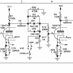
Filaments should be wired as usual. Use the curcuit you linked to - it's in parallel with the filament supply.
Ad Widget
Collapse
Announcement
Collapse
No announcement yet.
Integrating noise-gate circuit
Collapse
X
-
Which circuit? The voltage inverter? I still need to double my voltage right? I need another 6.3 volts positive and negative for the noie-gate.Originally posted by GainFreak View PostFilaments should be wired as usual. Use the curcuit you linked to - it's in parallel with the filament supply.
Comment
-
The circuit you linked to doubles the voltage on both sides and you get positive and negative voltage. As mentioned before maybe you won't need doubling the voltage:
http://img13.imageshack.us/img13/922...regulatorl.jpg
You can always use a small PCB power trasformer and build a separate supply around it and then stick it somewhere into the chassis with silicone or similar.
Comment
-
Alright. So I have to place this circuit in parallel with the 6.3v filaments supply? I can as well take the WP117 lead in that circuit and solder that to the heater of one powertube socket, and take WP119 and solder that to the heater of the other socket. And WP118 to the center tap of the filaments supply?Originally posted by GainFreak View PostThe circuit you linked to doubles the voltage on both sides and you get positive and negative voltage. As mentioned before maybe you won't need doubling the voltage:
http://img13.imageshack.us/img13/922...regulatorl.jpg
You can always use a small PCB power trasformer and build a separate supply around it and then stick it somewhere into the chassis with silicone or similar.
That will get me 6.3 volts for the tube heaters so that's okay, no change there? But also give me + and - 15 volts for the gate?
Comment
-
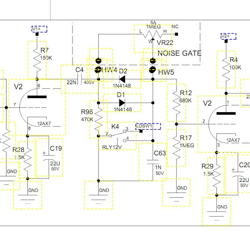
of course the anti parallel diodes used in the Peavey Rockmaster/Bravo preamp is designed as a "coring" circuit which trims the waveform and removes some noise. In later versions a parallel 1M resistor is added, then the XX got a slightly different version:

the JSX gets a fancier version with an adjustable noise gate

which can easily be added once you convince yourself its not an evil "diode clipping" circuit
Comment
-
Originally posted by Guitarist View PostHa! I remember seeing those diodes in the Rockmaster. I thought is was a clipping circuit. So now I understand. What is the switch for?
I can tell you what it does. When the switch is off, it puts the 1 nF cap in the noise gate to shunt only the high frequency noise to ground. When the relay contacts are engaged, it shorts around the cap to shunt all noise frequencies to ground.
-g
Comment
-
Integrated Noise Gate
This seems so simple and yet so brilliant!Originally posted by Steve Conner View PostHi,
The circuit is a little confusing because there are two inputs to the noise gate. The plain guitar signal, before the distortion stage, is fed to the gate chip's level detector. (...) The distorted signal is then fed to the actual gate part of the chip (...)
Are you guys aware of any distortion pedals with integrated noise gate that work like this? I think that this integrated solution might work much better than a traditional in-line combination of Distortion+Noise Gate pedals, even better if we use with high gain distortion.
Does anyone here have a copy of the image that BeŽlzeM posted on the very first post showing the circuit?
Thank you!
Thales.
GAMMOTH Death Metal
Comment
Comment