Ad Widget

Collapse

Announcement

Collapse
No announcement yet.

Home made rectifier replacement

Collapse
X
 
  • Filter
  • Time
  • Show
Clear All
new posts

  • Home made rectifier replacement

    Yesterday I made a couple of rectifier tube replacement plug ins. I used a couple of old tube sockets and six 1N4007 diodes. I wired 3 diodes in series then ran them from pin 4 to pin 8 and pin 6 to pin 8 with anodes pointing toward pin 8.

    The question is what to do about a cap for the socket? Sure enough if I leave the diodes exposed someone (me) will put their fingers in it or drop something metal in it. Can I fill the sockets with some sort of non-conductive epoxy?

    Thanks!

  • #2
    Originally posted by Axtman View Post
    Yesterday I made a couple of rectifier tube replacement plug ins. I used a couple of old tube sockets and six 1N4007 diodes. I wired 3 diodes in series then ran them from pin 4 to pin 8 and pin 6 to pin 8 with anodes pointing toward pin 8.

    The question is what to do about a cap for the socket? Sure enough if I leave the diodes exposed someone (me) will put their fingers in it or drop something metal in it. Can I fill the sockets with some sort of non-conductive epoxy?

    Thanks!
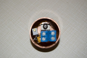
    once you are completely sure it works as designed, yes you can pot it up with any slow set epoxy (all but special silver, or metal filled epoxies are non conductive) this is a complete LM338 variable regulator I potted up in a copper pipe cap:


    you are aware that the voltages go up quite a bit with the tube -> SS rectifier switch right?

    Comment


    • #3
      Hey Axtman,

      Hope you meant you have the 1N4007 CATHODES pointing towards pin 8!
      I'd throw in a couple small 22 ohm 1/2W flameproof resistors in series w/ each leg.
      For over-current protection. But that's me.

      Comment


      • #4
        Try the lid from a Kodak 35mm film can as a cap. You can glue it on with hot glue or superglue.

        Comment


        • #5
          Well I mean that the arrow on the anode is pointing to pin 8. I guess that I should have said that the cathode end was on the pin 8 side.

          Yes I am aware that the voltage goes up. I might try the resistor trick.

          I found that the clean 35 mm caps fit snugly on the tube base. This works out because then I can service or mod the thing if I want. Epoxy just seems like a mess to me.

          Comment

          Working...
          X