Ad Widget

Collapse

Announcement

Collapse
No announcement yet.

Some Silvertone 1484 questions

Collapse
X
 
  • Filter
  • Time
  • Show
Clear All
new posts

  • Some Silvertone 1484 questions

    My favorite amp. I have two, actually, and use one of them in my band. I just finished a thorough rebuild of that one and it's working and sounding great. I made some mods, however, and have a question.

    I changed the standby switch to a "Fender style'. Before it shorted the signals coming from the phase inverter together before they entered the grids on the power tubes. I moved it to cut the power going into the choke. Now, I get a slight "pop" when I switch it on or off....which I've heard on Fender amps as well. Is there a cure for this, or it's just part of the game with a Fender style standby?

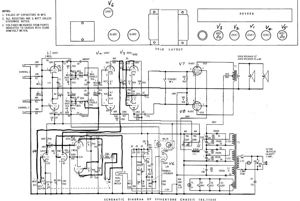
    Also, I am getting ready to go through my second 1484. Someone has already done a number of things to this one, such as replacing all the electrolyitcs. On my first one I used the stock values (4 X 100µF @ 150volts and 1 X 100µF @ 50 Volts). On this one, whomever put in 5 X 150µF @ 200 volts. This amp has a solid state rectifier and I'm attaching a schematic. My question is, was this necessary and will it have any other effect other than increased filtering?

  • #2
    If you do some searches here at Ampage, in the archives and in current stuff, and also over at Hoffman amps bbs in current and archives, you'll find several posts on these amps, including some that I've posted in quite extensively.

    These amps use two voltage doubler windings stacked on top of each other rather than a "solid state" rectifier. Doublers do use solid state components, but they are not the same as your typical full wave CT rectifer circuit using solid state diodes. Doublers don't regulate as well as non-doubler power supplies, and as a result will have more hum sometimes, but also will need to use larger filter caps to get the same performance as a non-doubler setup. Since these Silvertones are using four doubler sections, you can pretty much divide those main filter caps by 4 and you end up with what the actual value is, which is 25uf. That is pretty low when compared to many amps, and you will get better performance and lower hum with larger filter caps partly due to the larger caps themselves, but also due to the better regulation that the larger caps provide. You could go up to 400uf @ 200v and you still wouldn't be as high as the 110uf setup that Fender used on their Blackface amps. So what I'm saying basically is go even bigger if you want on their first filter caps in there. The bias cap shouldn't be any larger than 100uf however as you don't want to get such a large time constant on the bias supply. The bias cap is the 50v one on the schematic. (C30) Speaking of the schematic, there are a couple errors on it. There is one on the trem section where they transposed the pin numbers from cathode to plate, and another between the 330k resistors where the bias feeds the power tubes. They show it grounded and it is not.

    That amp can actually benefit from adding a voltage doubler circuit with an adjustable pot for the bias supply as the max voltage from it is too low so the power tubes run hotter than they should. You can get a little more power out of it without changing the sound if you move the screen tap to the same tap as the power tubes and then add a filter cap and dropping resistor. The value of the resistor will set the screen voltage. If you go too high then you run the risk of blowing that tiny stock output transformer. On the one I modded for my brother, I set the screen voltage at around 415v, instead of the 340v where it is now. Doing that and adjusting the bias with a voltage doubled and adjustable bias supply that I added, I was able to get 30 watts RMS with the amp. Stock it is only about 23-25 watts.

    As far as the standby setup.....you can sometimes get around the pop by adding a resistor around the switch (from one side to the other) but then you're back to an imperfect standby situation as far as the amp not muting the sound completely just like it does with the stock standby setup. I left my brother's with the stock standby setup......you only ready need the standby as a mute feature...these amps don't have voltages high enough to require a proper standby switch to stop cathode stripping. An Ampeg SVT with it's 700v plate is just starting to need a standby switch but most amps ith less voltages than that don't need one except for a stage muting feature. Given that, there was nothing wrong with the other standby approach that Silvertone used.

    If you were curious, I added a Fender reverb circuit and tank to my brother's 1484, along with adding an EF86 and modding channel 1, and then also modding channel 2 for more gain and revoicing the EQ section. In order to accomplish all of this, I had to re-wire and re-arrange the whole preamp area to make sure the signal flowed correctly through the amp. The stock layout leaves quite a bit to be desired and with the power transformer location, you will always have this amp humming more than many others, especially if you increase the overall gain like I did. The only way you could get around it would be to surround the power transformer or the preamp circuitry for channel two inside the amp and by the pots with some Mu-metal, and that stuff is spendy.

    Enjoy your project......I'm glad you're working in that rats nest and not me.

    Greg

    Comment


    • #3
      Thanks

      Speaking of the schematic, there are a couple errors on it. There is one on the trem section where they transposed the pin numbers from cathode to plate
      Wow. Perfect timing... I've been busy rebuilding my own 1484, and using the same schematic. The wiring around the trem section is my last part, and it was driving me nuts. For the most part, I was just replacing components as they were, but sometimes I would unsolder a bunch of them and refer to the schematic to get the new ones hooked up right. Thanks for the heads up about the error (pins 6 and 8 swapped, right?)!

      I'm glad you're working in that rats nest and not me
      No kidding. I usually build stompboxes - with nicely layed out PCBs. This is my first tube amp project. I guess most any other tube amp would be a picnic compared to this...

      Comment


      • #4
        Originally posted by waltk View Post
        Wow. Perfect timing... I've been busy rebuilding my own 1484, and using the same schematic. The wiring around the trem section is my last part, and it was driving me nuts. For the most part, I was just replacing components as they were, but sometimes I would unsolder a bunch of them and refer to the schematic to get the new ones hooked up right. Thanks for the heads up about the error (pins 6 and 8 swapped, right?)!


        No kidding. I usually build stompboxes - with nicely layed out PCBs. This is my first tube amp project. I guess most any other tube amp would be a picnic compared to this...
        Yah, the pins are just swapped on the trem tube there. These amps are some of the biggest rats nests out there, but they do sound good stock and can sound really nice with some light changes.

        You can get more gain and better sound if you go towards Fender territory in the preamp....change the dropping resistors to lower values and get higher plate voltages, change the cathode resistors to lower values and add cathode caps and get more gain and better and more open sound. The trem is fantastic on these and the reverb sucks balls.

        Have fun!

        greg

        Comment

        Working...
        X