Ad Widget

Collapse

Announcement

Collapse
No announcement yet.

Cathode Follower Question (59 bassman)

Collapse
X
 
  • Filter
  • Time
  • Show
Clear All
new posts

  • Cathode Follower Question (59 bassman)

    I have just done a rebuild/modbuild on a 73 Fender Pro-Reverb.

    It now has a nice blackface channel, and I have converted the 'vibrato' channel into a Plexi/59 Bassman circuit.. quite an upgrade from the old silver face:

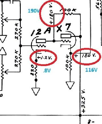
    The amp sounds exceptional. But I have a question about some voltages. On the cathode follower, it's showing the 180V figure twice, and I suspect that is how it should be. Called for voltages are shown circled in red, and my actual voltages are written in blue.

    Do I need to worry about it?.. and how would I correct it?

    The shown circuit is lifted from this complete schematic in case someone would like to view the entire thing: http://www.drtube.com/schematics/fen...-schematic.gif


    Thanks,

    Aaron

  • #2
    Any ideas? I've looked at a few more amp schematics, and I'm finding that the mismatched voltages should be the same. what could cause this?

    Comment


    • #3
      Originally posted by akimball442 View Post

      The amp sounds exceptional. But I have a question about some voltages. On the cathode follower, it's showing the 180V figure twice, and I suspect that is how it should be. Called for voltages are shown circled in red, and my actual voltages are written in blue.

      Do I need to worry about it?.. and how would I correct it?
      Nope, (BTW, that's a DC coupled cathode follower), the second anode is connected directly to the HT, while the 2nd grid is at 180V. Also, be aware that voltages shown on the older Fender schematics call for a +/- 20 % tolerance, so you should not take them as "the absolute truth". Having said this, I agree that the 2nd cathode voltage looks low.

      Be also aware that the voltages shown on the schematic date back to a time when the mains voltage was "right on target", while today's mains voltages are usually 10-12V higher, and that could be the reason for the higher (190 vs 180V) 1st anode/2nd grid voltage.

      Hope this helps

      Best regards

      Bob

      Edit - I just realized I misread the schematic, post edited accordingly
      Last edited by Robert M. Martinelli; 02-17-2010, 09:47 AM.
      Hoc unum scio: me nihil scire.

      Comment


      • #4
        Show us a shot of the circuit, voltages need not match exactly, but your low voltage at the cathodes is suspect.

        Comment


        • #5
          Is your CF stage cathode resistor actually 100k or does it measure something less?
          Building a better world (one tube amp at a time)

          "I have never had to invoke a formula to fight oscillation in a guitar amp."- Enzo

          Comment


          • #6
            Good point TW....

            Some amps used 10% resistors, some others even 20% ones, and, to make things even worse, old carbon resistors do have a known tendency to drift.

            Cheers

            Bob
            Hoc unum scio: me nihil scire.

            Comment


            • #7
              You haven't mentioned, so it should be asked - is the correct tube type in there? 5751 and 12AY7 etc can draw more current than a 12AX7.
              If correct type, have you tried different 12AX7s in there, maybe a bad tube?
              Also, what is the supply voltage, on the cathode follower plate?
              My band:- http://www.youtube.com/user/RedwingBand

              Comment


              • #8
                Originally posted by Robert M. Martinelli View Post
                old carbon resistors do have a known tendency to drift.
                And so do new ones if you overheat them when you solder them in
                Building a better world (one tube amp at a time)

                "I have never had to invoke a formula to fight oscillation in a guitar amp."- Enzo

                Comment


                • #9
                  Originally posted by Robert M. Martinelli View Post
                  .....the second anode is connected directly to the HT.....
                  Oh don't I feel like an idiot. I've looked at the schematic a hundred times, and somehow I had to see that in writing to figure out my error....

                  I had the 2nd anode connected to the HT via another (third) 100K resistor.

                  Shorting the resistor out corrected the voltages. I will be removing it now..

                  Thanks for your help.

                  Comment


                  • #10
                    Well, I guess that's why they say "you live, you learn....."

                    I'm glad we managed to point you in the right direction! And DON'T feel like an idiot...I've made my share of mistakes too, often due to my being over-confident...

                    Cheers

                    Bob
                    Hoc unum scio: me nihil scire.

                    Comment


                    • #11
                      Totally off topic, but I just hope no black folks (at least those who don't know vintage Fender jargon) get sight of the "Blackface" channel - your gig might end early. Too bad it's not known as "Blackplate."

                      Comment

                      Working...
                      X