Ad Widget

Collapse

Announcement

Collapse
No announcement yet.

changing Princeton Reverb to Deluxe Reverb, please help...

Collapse
X
 
  • Filter
  • Time
  • Show
Clear All
new posts

  • changing Princeton Reverb to Deluxe Reverb, please help...

    hi,
    i started my project as a princeton reverb chassis naked, build a exotic wood cab, with 12" weber speaker...
    for the electronic part, i decided to go with a deluxe reverb since i prefer the DR PI sound... more efficient to my ears..
    i put a DR power tranny, DR output tranny and even found some place for the choke under the chassis... the cap is the cap can with some caps added to reach the filtering power of the dR...
    BUT my problem is: the deluxe reverb go with two chanels when the PR chassis has only one channel.. so i tried to wire this first schematic i derived from the DR...
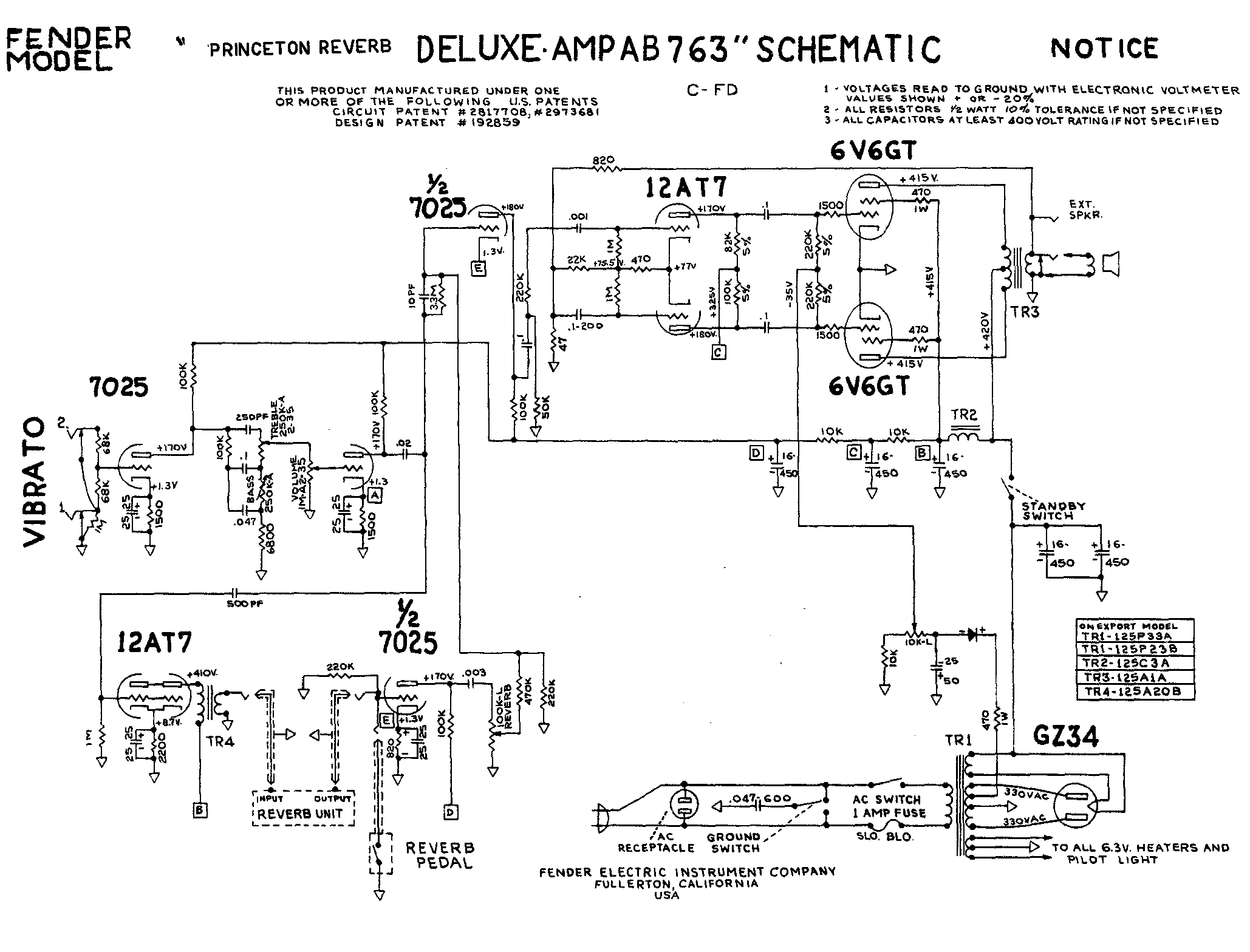


    but the sound is not as opened as a classic DR... a little too mufled..
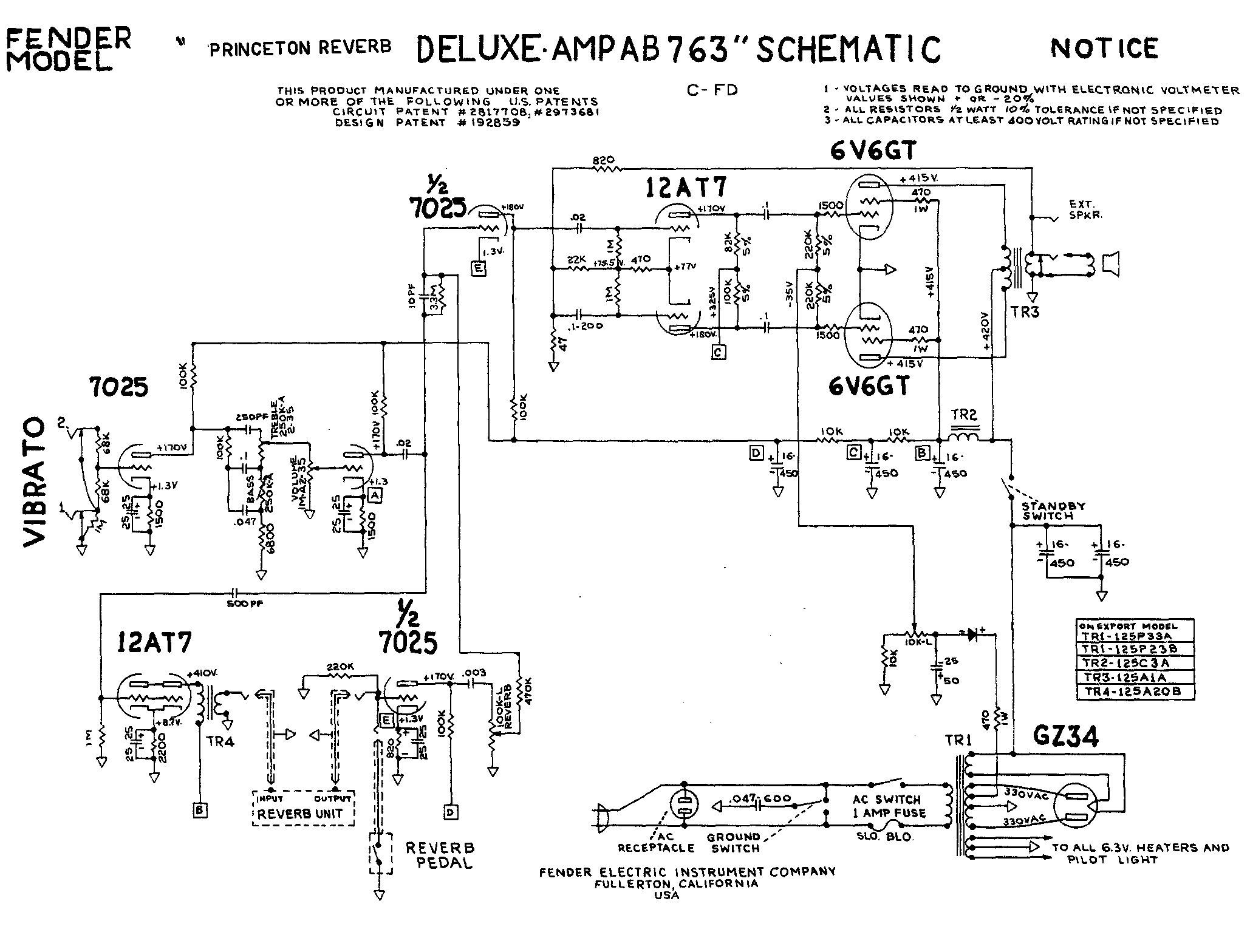
    so i tried this second schematic i derived from the PR by just changing the PI...
    big buzzz (no ground before the .02 cap??) and way too hot sound, very very loud with volume on 2...


    i tried the first schematic with a 100K instead of the 22OK serial resistor... a bit better sounding... but i'm ain't no pro so maybe you can help deciding how to connect the preamp to the PI??

    Thanks for help or ideas..
    Ben

  • #2
    The second schematic looks good to me.
    The purpose of those two 220K resistors in series with the signal flow is mixing the two channels (they attenuate the signal to some degree, so there might be some room for tweaking).
    You got only one channel and hence wouldn't need a 220K there.
    Make sure you used 1.5K cathode resistors on each cathode of V1 and one 820 ohms for both cathodes of the reverb recovery tube.

    Comment


    • #3
      Originally posted by txstrat View Post
      The second schematic looks good to me.
      The purpose of those two 220K resistors in series with the signal flow is mixing the two channels (they attenuate the signal to some degree, so there might be some room for tweaking).
      You got only one channel and hence wouldn't need a 220K there.
      that's what i thought... so i tried the second schematic but there's way too much gain... i think this solution work with the old PR PI because it's rather inefficient... but you need to attenuate the signal before using the DR PI...
      the 220k/.001 solution has not enough gain, the amp seems dull.. so i tried to tweak here with a 100k (for more gain) and .02 cap (for more bass) just like below...


      seems to work good, but i still need to push the amp to check the headroom...

      I have another concern, with the second schematic (only the .02 cap as in PR), a big humm occurs, i don't know why..
      i noticed that this humm occurs also if disconnect the 50k ( left from the vibrato circuit ) to ground on the first schematic... the signal seems to need to be grounded here, i don't really understand why... anyway...

      Originally posted by txstrat View Post
      Make sure you used 1.5K cathode resistors on each cathode of V1 and one 820 ohms for both cathodes of the reverb recovery tube.
      yeah that's what i used... no problem, i want to keep as close as possible to the DR sound..

      i'd be really interested to find a schematic of a single channel Deluxe reverb clone, Fender did not to my knowledge did a Deluxe reverb type amp woth only one channel... the only one i know is Allen accomplice, anyone know how Allen solved this problem??

      Thanks
      Ben

      Comment


      • #4
        The second schematic in your first post is EXACTLY what you got to do, when building a one channel DR with no vibrato (maybe you could decrease the coupling cap to the PI to .001, but that's partly a matter of taste).
        No 220k resistor in series and no 50k to ground. The two 220k mixing resistors do attenuate the signal to a degree but they wouldn't cause the amp to sound dull.
        If there's too much gain there must be something causing this. That's why I asked for the cathode resistors. Look at the preamp plate resistors. All 100K? Not 220k accidentally? A plate resistor of 220k makes for way more gain in that stage.
        I'd check all values of parts in your build again.
        Regarding the hum - does the hum change with knob settings?

        Comment


        • #5
          What txtstrat says...if you have built exactly to the most recent schem, then you shouldn't have any issues...assuming good voltages, layout & grounding...

          So, next step is to post some pics of the build & describe grounding plan & post voltages (we can't identify an issue by looking at a correct schem, if the amp you have built differs from the design intent).

          Comment


          • #6
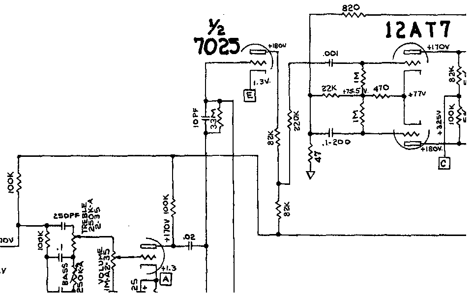
            If you don't attenuate before the PI at all you will have too much gain IME. A good way to attenuate and avoid the extra 220k/.1 cap/50k ground thing is to use a split plate load (see image)
            Click image for larger version

Name:	possible.GIF
Views:	1
Size:	14.2 KB
ID:	818893
            You can jostle the values to adjust the gain, as in, instead of a 78k/22k you could use a 68k/33k or a 82k/18k. As long as the total resistance is close to 100k.

            Also, check your preamp voltages to be sure they're up where they should be. If they're low the amp will sound muddy compared to a DR.

            Chuck
            "Take two placebos, works twice as well." Enzo

            "Now get off my lawn with your silicooties and boom-chucka speakers and computers masquerading as amplifiers" Justin Thomas

            "If you're not interested in opinions and the experience of others, why even start a thread?
            You can't just expect consent." Helmholtz

            Comment


            • #7
              Wouah thanks for all the answers and ideas...

              NWJB, i'm almost sure of the value of my components, but i'll check another time, for sure...
              what i'm sure is that the voltages are correct with the deluxe reverb schematic, i had to change the two power resistors to 18k and 22k to match my voltages to the schematic voltage...

              Yesterday i found some Allen Accomplice chassis photo and blue printed this part just before the PI...
              it's close to the "Chuck H" schematic.. with two 82k resistor (i'm not 100% sure about the values since the pix are low definition and i can't see clearly the colors) and a serial 220k resistor.

              see

              that seems to confirm my intuition that there's too much gain if you don't attenuate before the PI...
              the amp sounds quite good at low volume (hard to find times to push the amp)... but maybe i'll have to tweak the values... (the 100k for the sum of the two resistor sound good to me as a start...)

              the hum problem has disapeared, i think it was related to the cap to resistor to cap in serial, without grounding of any sort... the signal is too low and get all the parasits.... with this later approch no problem...

              i'd like to submit something more to your expertise, i can't get rid of an oscillation on the high frequencies (typical high E string goating sound) just like a tremolo at very high speed... any idea to what it can be related? the tranny placements? the filtering? the blocking resistors? the tubes? an electronic problem? the speaker?

              i'll try to post some pix of the chassis and the tranny placements when i'll be home tonight...
              anyway thanks for all the sharing..
              Ben

              Comment


              • #8
                "NWJB, i'm almost sure of the value of my components, but i'll check another time, for sure...
                what i'm sure is that the voltages are correct with the deluxe reverb schematic, i had to change the two power resistors to 18k and 22k to match my voltages to the schematic voltage..."

                DR run more like 220-230vdc on the preamp tubes, if yuo only have 170vdc on V1 V2 plates, your amp may be somewhat darker & grindier. If you have appropriate voltages at the power tube platess (410-425vdc) then maybe go back to nearer stock values in the power supply, bearing in mind voltage drop to V1 will be a little less now as you do not have 2 preamp tubes drawing current from the last B+ node.

                That's why I asked for the voltages that you actually have...few Fender amps ever match the schematic voltages.

                Comment


                • #9
                  +1
                  I have not actually poked around inside a vintage DR but if I figure for modern wall voltages, and the resulting trend to bias on the cool side to control current due to these new higher voltages (therefore lower voltage drop to the preamp), I guess the preamp plate volts in the 200+ a little range. This will change the tone and feel of the amp dramatically because of how tubes behave at higher voltage COMBINED with the fact that the higher voltage will shift the preamp tubes bias points (since we changed the plate volts but not the cathode resistor values). I'd shoot for 190V to 200V on the plates of V1 with the stock 10k resistor value on the last PSU resistor. Use the PSU resistor that drops volts from the screens to the preamp to adjust your preamp volts.

                  Chuck
                  Last edited by Chuck H; 08-11-2010, 07:44 PM.
                  "Take two placebos, works twice as well." Enzo

                  "Now get off my lawn with your silicooties and boom-chucka speakers and computers masquerading as amplifiers" Justin Thomas

                  "If you're not interested in opinions and the experience of others, why even start a thread?
                  You can't just expect consent." Helmholtz

                  Comment

                  Working...
                  X