Ad Widget

Collapse

Announcement

Collapse
No announcement yet.

Peavey VTM - from 6L6 to EL34

Collapse
X
 
  • Filter
  • Time
  • Show
Clear All
new posts

  • #16
    Alright, but how do I know what value is best? Is it tuning by ear? Or should I be measuring something for an optimal value?


    EDIT: wait, you are still talking about the power supply board. We have a miscommunication here, and I don't know how. I have said, a couple times, that I corrected the voltage divider on the power supply board and added a bias control. It has a 3K and 50K pot with a 22K limiting resistor. I could not get it hot enough with just 50K.


    Now I have been talking about the power tube board this whole time.

    I hope we are on the same page now..
    Last edited by azrael; 08-13-2010, 10:52 AM.

    Comment


    • #17
      Ah, the power tube grid stopper then. The difficulty arises when we were talking about adjusting bias for different tubes at one point, and there is a 47k in the bias supply, and then asking about "the 47k" and some change elsewhere. There is more than one 47k resistor in evidence. And the amp does not use one overall part number list, there is a separate one for each board, so there are more than one of R7, R8, and various others. And I am just an old fart with 20-30 ongoing online assistances going at any one moment.

      You want to change the grid stoppers on the power tubes? GO ahead, but have you a good reason? I mean other than that something different appears in an unrelated amp? See how it sounds with the 47k grid stoppers, it will be easy enough to go back and change them if you need to. Most times, in the signal path, in my head anyway, if you want to have audible differences, you need to change a part by a factor of 2 or more. If you want to putz with that grid stopper value, then I might recommend steps at 22k, 10k, and your 5.6k or 4.7k. I picked standard resistor values. Changing from 47k to 41k is not likely to do much.

      And you have hit upon 5.6k apparentl;y from the Marshall schematic, but the 5.6k Marshall grid stoppers are the 47k grid stoppers in the Peavey, and both of those are the aforementioned 1.5k resistors between pins 1 and 5 in the original conversion article - the Fender grid stoppers. Unless I misread that too, he left them at 1.5k. SO grid stoppers can be all over the map, depending upon the thoughts of each designer. Take your pick.
      Education is what you're left with after you have forgotten what you have learned.

      Comment


      • #18
        Originally posted by Enzo View Post
        Ah, the power tube grid stopper then. The difficulty arises when we were talking about adjusting bias for different tubes at one point, and there is a 47k in the bias supply, and then asking about "the 47k" and some change elsewhere. There is more than one 47k resistor in evidence. And the amp does not use one overall part number list, there is a separate one for each board, so there are more than one of R7, R8, and various others. And I am just an old fart with 20-30 ongoing online assistances going at any one moment.
        Oh, okay, haha. Fair enough.

        Originally posted by Enzo View Post
        You want to change the grid stoppers on the power tubes? GO ahead, but have you a good reason? I mean other than that something different appears in an unrelated amp? See how it sounds with the 47k grid stoppers, it will be easy enough to go back and change them if you need to. Most times, in the signal path, in my head anyway, if you want to have audible differences, you need to change a part by a factor of 2 or more. If you want to putz with that grid stopper value, then I might recommend steps at 22k, 10k, and your 5.6k or 4.7k. I picked standard resistor values. Changing from 47k to 41k is not likely to do much.

        And you have hit upon 5.6k apparentl;y from the Marshall schematic, but the 5.6k Marshall grid stoppers are the 47k grid stoppers in the Peavey, and both of those are the aforementioned 1.5k resistors between pins 1 and 5 in the original conversion article - the Fender grid stoppers. Unless I misread that too, he left them at 1.5k. SO grid stoppers can be all over the map, depending upon the thoughts of each designer. Take your pick.
        In what way would lowering the grid stopper resistors change tone? How does it affect the performance of my amp? If it's something not necessary to modify, I won't do it.

        Also, should I change the screen resistor values at all?

        Also, how do you feel about the lowering of the bias feed resistors, those two 220K ones before the grid stopper resistors?
        It's a suggestion here:
        Tales From The Tone Lounge; The Ultimate JCM800?

        Then there's this:
        http://tone-lizard.com/images/Improv...resor_Grid.gif
        The above circuit will reduce secondary emission of the tube even better than the original wiring scheme. You also get improved linearity. This will end up making the tube's plate current more efficient to the point that you will have to rebias! The last Marshall I 'modified' in this manner had the plate current increase 5mA. So, please recheck your bias after doing this procedure. Where some technicians insert a 1-ohm resistor between pin #8 (cathode) and ground, this arrangement is far 'safer' for the tube. Think about it. Instead of having the Suppressor Grid at ground potential or even at a negative voltage, you would have a positive voltage (granted only 50mVDC or so, but positive nonetheless) on that grid, because no one ever separates the Suppressor Grid from the Cathode. Where most inexperienced technicians have trouble with EL34's is in a 'poorly' designed amplifier that was biased by the current draw method via a 1-ohm resistor in the cathode! The idea presented above, in concert with an 'improved' Screen-Grid wiring scheme, yields a very efficient environment for any EL34. That wiring scheme is seen ahead in 'Mods and Odds', but I'll give you a sneak preview. Remember that those 100-ohm resistors seen below are the Screen-Grid resistors soldered on the tube socket.
        Sorry for all the questions, I just want to do it right one time, and make sure that I have a reliable amp.

        Comment


        • #19
          The screen resistors are the ones you really want to change for EL34s, the 1k or 1.5k will limit screen current.


          As to the other stuff, I am not going to take you any further, I don;t get into all that stuff, I leave it for the amp fans. I have enough on my hands doing maintenance and repair and troubleshooting. There are plenty of things one can do for an amp, and I consider them all items on the "vanishing returns" list. What is "improved liearity" in the powr amp anyway, at least in terms of tone? And while it may be a change, is it really "better" in any meanaingful way? And we have to wonder if some of these solutions are not out there looking for problems to address. I for one can't honestly say that tube life has been an issue in Peavey amps, and when you rewire this for EL34, will it have a tube life problem if left stock? I sure don;t know.

          Plenty of guys are here on this forum who are into all the tweaking and noodling part values, and they are better equipped to answer your questions about all that.
          Education is what you're left with after you have forgotten what you have learned.

          Comment


          • #20
            Okay, well, that's fair enough, hehe. Thank you, you've been a great help. I'll let you know how it all goes.

            Comment


            • #21
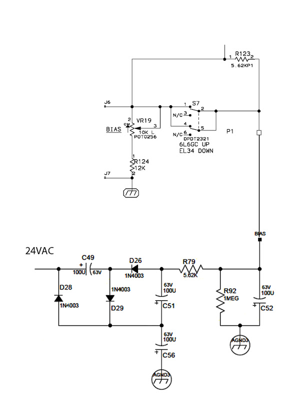
              The JSX has a nice switch for EL34/6L6 modes, along with a variable bias pot coming off the 24VAC tap:


              I built this onto a little PCB for use in my Ultra


              I am adding it to my Ultra (after checking the pin 1 thing Enzo mentioned!) along with parallel metal oxide 3w 1.5k screen grid resistors (~6w 750 ohm)

              Comment


              • #22
                IMO output tube grid stoppers should be kept as low as you can get away with and keep the output section stable. Higher values do cause a change in tone, not for the better. 5.6k is fine for EL34, but you can go lower if you want. My 1971 Traynor has 1.5k's for stoppers and it runs EL34s. A different one I have had no grid stoppers fitted originally and wouldn't run stable with new production tubes until I added stoppers. I think I put in 2.7k's.
                The farmer takes a wife, the barber takes a pole....

                Comment


                • #23
                  Okay, cool. I'll keep that in mind. Thanks!

                  Comment

                  Working...
                  X