Ad Widget

Collapse

Announcement

Collapse
No announcement yet.

Silvertone 1481 with new OT. HELP!!!

Collapse
X
 
  • Filter
  • Time
  • Show
Clear All
new posts

  • Silvertone 1481 with new OT. HELP!!!

    Hello all,

    I'm rebuilding a Silvertone 1481. I have replaced all the resistors and capacitors with new parts (not the electrolytics but they're not leaking) and all the tubes. I also installed an 8" Jensen 4ohm speaker and a Heyboer hy022905M OT.

    The OT came with red and blue leads on one side and green and black leads on the other. Several websites suggest that the blue lead is plate lead (AC hot) and red is the B+ signal from the 6v6. Green and black are the speaker leads. This is my first amp build. Is the 6V6 not enough tube to drive the 4ohm OT?

    All the tubes are lit up and I know it's not a signal problem because the speaker does NOTHING. No speaker hiss.

    http://www.freeinfosociety.com/elect...ertone1481.pdf

    If my color coding is right, I'm wired exactly as the schematic describes. I'm going crazy and the girlfriend has just about had her fill. Thanks.

    Paul
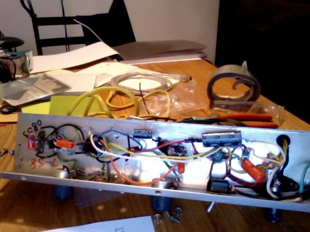
  • #2
    Hi Paul: the color coding on OTs is set by EIA standards; link to a Weber OT with color coding the same as yours:

    https://taweber.powweb.com/store/022905sch.jpg

    On the primary side, the red lead goes to the junction of the 5Y3 rectifier output (can be either #2 or #8) and the first filter cap. The blue lead goes to the 6V6, pin #3 - the plate. If you have them reversed ... you have a mess.

    6V6 tube data sheet; http://www.tubebooks.org/tubedata/HB..._2/6V6-GTA.PDF

    See page 2 identifying pin #3 as the plate.

    On secondary/output side, the green lead goes to the + terminal on the speaker and the black lead to the - terminal.

    If the 6V6 is connected correctly, it will drive anything you want it to drive.

    Good luck with your amp. J

    Comment


    • #3
      Originally posted by windupsmiles View Post
      I'm rebuilding a Silvertone 1481. I have replaced all the resistors and capacitors with new parts (not the electrolytics but they're not leaking)
      First, Just because the filters arent leaking doesn't mean they're good. Those caps have a lifespan of ten to twenty years. And why did you replace all the resistors and film caps? Following your logic I'll ask, were they all leaking? There will sometimes be resistors and film caps that need replacing bcause they've drifted in value. Sometimes a film cap will stop blocking DC. But for the most part resistors and film caps last virtually forever. If you've done any reading on the subject you should know that replacing the electrolytic caps in an amp that age is critical while the resistors and film caps are not. Trust me, the last thing you want is a bias failure because of a bad bias supply filter or for one of the B+ filters to pop and blow gunch all over the inside of the amp. I know that the big electros are expensive and sometimes hard to come by but IMHE you do need to replace them.
      "Take two placebos, works twice as well." Enzo

      "Now get off my lawn with your silicooties and boom-chucka speakers and computers masquerading as amplifiers" Justin Thomas

      "If you're not interested in opinions and the experience of others, why even start a thread?
      You can't just expect consent." Helmholtz

      Comment


      • #4
        Oops....

        I replaced all the resistors because most of them had drifted in value pretty severely. I want to see if i can get it to make sound before replacing the electrolytics. Before, as the schematic shows, the red lead of the OT was supposed to be attached to the electrolytic, are you saying i should bypass it and go straight to the tube?

        I DO have the wires switched right now. Have i seriously screwed up this amp?

        Paul

        Comment


        • #5
          No, no, don't bypass the PS filters. But do replace them when you can.

          If you didn't smell burning plastic or see smoke you probably haven't ruined anything.
          "Take two placebos, works twice as well." Enzo

          "Now get off my lawn with your silicooties and boom-chucka speakers and computers masquerading as amplifiers" Justin Thomas

          "If you're not interested in opinions and the experience of others, why even start a thread?
          You can't just expect consent." Helmholtz

          Comment


          • #6
            Thus...

            So, just to pick your brains one more time, if I may... a LIKELY source of my problem would be that the OT is not getting any juice from the rectifier tube (6x4) because the electrolytic is no good? What do the two numbers refer to on the filter caps (ie 5/450)? Ohms to volts? What are some good replacements?

            Thank you guys for your help,
            Paul

            Comment


            • #7
              Originally posted by windupsmiles View Post
              So, just to pick your brains one more time, if I may... a LIKELY source of my problem would be that the OT is not getting any juice from the rectifier tube (6x4) because the electrolytic is no good? What do the two numbers refer to on the filter caps (ie 5/450)? Ohms to volts? What are some good replacements?

              Thank you guys for your help,
              Paul
              It means 5mf at 450v. Do not use any replacement with a lower voltage rating. Seriously, before you go any farther you should read up on basic electronics and basic troubleshooting techniques. This is not meant to insult you. Tube amps can be very dangerous and the high voltages can easily stop your heart if you are cluelessly poking around.

              Comment


              • #8
                The 1481 is a great amp to learn on. You are probably closer than you realize to getting it working - you just need to wire up the power supply correctly.

                As John said, the red wire to the OT comes off the rectifier high voltage, pin 7. This is also where the first filter cap (20uF / 450 Volts) and the 4.7K resistor to the second filter cap are connected. It is a busy junction, so sometimes you'll do the red OT wire right to lug 7 of the 6X4 socket, and a separate lead from that socket to the cap and resistor. Electrically it is all the same.

                You can wire it correctly to get your amp working, but I agree with Chuck that chances are strong you'll want to put new filter capacitors in there. It has a 20uF / 10uF / 5uF cap can which is not a part that's easily available. Most people will use a 22uF, 10uF and 4.7uF separate caps, all rated for 450V. The easiest way to do this, I've found, is to mount a terminal strip right over the cap can, and transfer the leads and resistors from the cap to corresponding ones on the terminal strip. Draw yourself a diagram and take some pictures before you disconnect anything.

                Here is a shot of a 1471 (same circuit as the 1481) where I did just this. It worked fine for me, and made for a great little recording amp.

                If you run into any issues take some gut shots and post them here.

                Good luck,

                RWood
                Attached Files
                Last edited by RWood; 01-06-2011, 03:02 AM.

                Comment


                • #9
                  Thanks

                  Thanks for your help (and cautionings), guys. I ordered some new filter caps and I'll let you know how it turns out.

                  Paul

                  Comment


                  • #10
                    +++
                    "Take two placebos, works twice as well." Enzo

                    "Now get off my lawn with your silicooties and boom-chucka speakers and computers masquerading as amplifiers" Justin Thomas

                    "If you're not interested in opinions and the experience of others, why even start a thread?
                    You can't just expect consent." Helmholtz

                    Comment


                    • #11
                      Almost...

                      SO i replaced the filter caps with the ones you recommended. I heard the speaker make a split second's worth of speaker hum just before the 4.7k resistor blew up. What happened?

                      Paul

                      Comment


                      • #12
                        http://s1115.photobucket.com/albums/...1-11at1756.jpg

                        If it helps...

                        Paul
                        Last edited by tboy; 01-12-2011, 10:16 PM.

                        Comment


                        • #13
                          http://s1115.photobucket.com/albums/...1-11at1756.jpg

                          The pic.
                          Last edited by tboy; 01-12-2011, 10:20 PM.

                          Comment


                          • #14
                            I can't really tell by the pic but did you observe correct polarity? Also, are the new caps rated for the same voltage as the originals?
                            "Take two placebos, works twice as well." Enzo

                            "Now get off my lawn with your silicooties and boom-chucka speakers and computers masquerading as amplifiers" Justin Thomas

                            "If you're not interested in opinions and the experience of others, why even start a thread?
                            You can't just expect consent." Helmholtz

                            Comment


                            • #15
                              This pic?


                              Tough to see but it looks and sounds like you wired up the filter caps wrong. You might want to read up on some theory here and study the schematic.
                              It's not a series connection where the high voltage runs through the cap on it's way to the next stage, as it is with coupling caps. With filters it's more like the high voltage from the rectifier runs past a sediment trap on it's way to the first dropping resistor. That trap is the first filter cap, the 22uF, where the + side is connected at the junction of the high voltage and the dropping resistor, but the - is connected to ground. Use your ohmmeter to see if you have continuity between the + end and ground (you shouldn't) and your cap's - end and ground (you should)

                              The OT red lead is also connected to that + connection.

                              The dropping resistor is the 4.7K that blew. This needs to be a fairly heavy duty resistor, so it could be that yours was not able to handle the current going through it and was ready to fail on its own, but I am guessing that a short in the power supply is what stressed it beyond its limits. Your replacement should be a metal oxide rated for at least 2 watts, preferably 3.

                              So after the 4.7K is the + end of the next cap, the 10uF, which is connected to the junction of the 4.7k, the orange wire to the power tube screen, and the next dropping resistor. The - end of the 10uF goes to ground. Again, once you get things straightened out check for continuity as before.

                              The next dropping resistor is the 100K. Between it and the yellow wires to the preamp tube's plate resistors you have the + for the last filter cap, the 4.7uF. The - end of that cap goes to ground.

                              Here is a great startup guide that you can use once you are back to that point:
                              Paul Ruby Amplifiers

                              Comment

                              Working...
                              X