Some important things I've discovered in the Split Channel over time:
* There are two basic versions of the amplifier. The first (was manufactured for a year and a half aprox. and have seen very few units) differs from his previous equalization. Impossible to get decent lead sounds.
* Second version is the most popular and has some variations between units:
- Switching system through transistors or an CA3046 integrated circuit
- Different distribution functions in the tubes 3 and 4. Some assign the last two steps of the lead channel in V3 (V4 is only for the reverb) and others distribute among them: penultimate lead step on the first triode of V3 and final lead step on the first triode of V4 (driver and recovery are allocated in the second triode V3 and V4 respectively). First version is desirable (with lead steps located in V3) to assign in more positive way the tubes, but you can rewire them without problem.
- Different driver circuits in 50 watts version. Some traditional, some asymmetric. 100 wats are always not traditional (assymetric)
- Different location of the three 0.22uF capacitors to mute channels. Some use little multilayer ceramic in the bottom of the PCB and others use polyester capacitors located on the top of PCB.
- Existence in some units of a 47K resistor in series with one side of the lead potentiometer gain.
...
*With the original value of these capacitors (0.22uF) is not possible to filter to ground (mute) completely all frequencies. Being active the lead channel, if the volume of the clean channel is raised, keep sounding low frequencies of that channel added to the lead (!)
The same applies in the opposite direction (low frequencies of lead added to clean sound with lead master raised)
There is another more serious variant (I've seen in one unit): In the footswitch jack 100uF electrolytic (channel selection) and 22uF (reverb on/off) are missing. During the lead / clean change, sounds a distortion in clean channel for the first four or five seconds that gradually fades. It can be a huge headache if goes unnoticed.
...
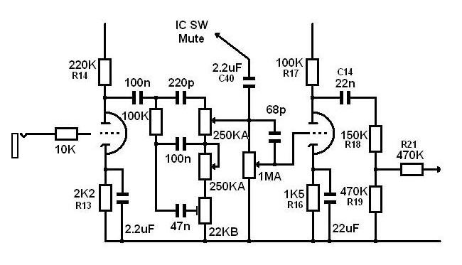
The best way to have a real and definitive clean channel on this amp is completely removing the first and second steps of the original channel and freeing V2. Inject the signal from the input jack directly to it and after the first triode install a Fender/Marshall tonestack type but adapted to the contours of the other channel to find a musical balance between them.
The one I've used is this. It has an internal adjustable resistor for the mids and a slightly cropped profile in the lows.

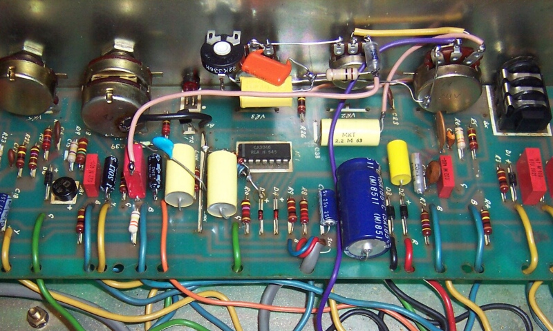
It´s better not to use the PCB to install the circuit. Simply remove a few components to disconnect the original circuit, remove the potentiometers and to do an external wiring. 100n capacitor is added to avoid DC voltage in the new circuit.

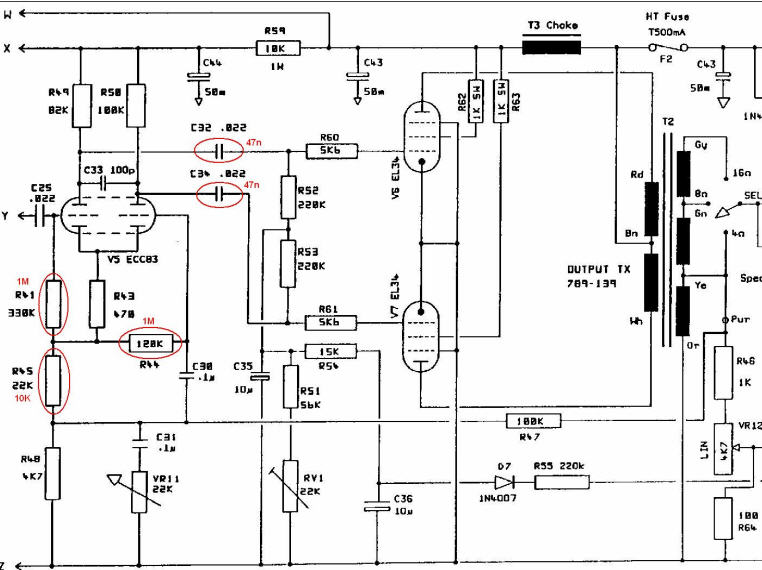
Accompanying this circuit, driver (when is asimmetric) is transformed as follows:

And a small modification in the loop circuit.
Capacitor C24 produces unnecessary emphasis for the lead in the highest treble/harmonics. With the new tonestack is also not necessary for clean channel.
Raising the value of resistor R29 the whole amp acquires higher output without compromising anything. It is good fot the clean channel to develop more volume.

I hope this can be useful to someone.
Best regards.
* There are two basic versions of the amplifier. The first (was manufactured for a year and a half aprox. and have seen very few units) differs from his previous equalization. Impossible to get decent lead sounds.
* Second version is the most popular and has some variations between units:
- Switching system through transistors or an CA3046 integrated circuit
- Different distribution functions in the tubes 3 and 4. Some assign the last two steps of the lead channel in V3 (V4 is only for the reverb) and others distribute among them: penultimate lead step on the first triode of V3 and final lead step on the first triode of V4 (driver and recovery are allocated in the second triode V3 and V4 respectively). First version is desirable (with lead steps located in V3) to assign in more positive way the tubes, but you can rewire them without problem.
- Different driver circuits in 50 watts version. Some traditional, some asymmetric. 100 wats are always not traditional (assymetric)
- Different location of the three 0.22uF capacitors to mute channels. Some use little multilayer ceramic in the bottom of the PCB and others use polyester capacitors located on the top of PCB.
- Existence in some units of a 47K resistor in series with one side of the lead potentiometer gain.
...
*With the original value of these capacitors (0.22uF) is not possible to filter to ground (mute) completely all frequencies. Being active the lead channel, if the volume of the clean channel is raised, keep sounding low frequencies of that channel added to the lead (!)
The same applies in the opposite direction (low frequencies of lead added to clean sound with lead master raised)
There is another more serious variant (I've seen in one unit): In the footswitch jack 100uF electrolytic (channel selection) and 22uF (reverb on/off) are missing. During the lead / clean change, sounds a distortion in clean channel for the first four or five seconds that gradually fades. It can be a huge headache if goes unnoticed.
...
The best way to have a real and definitive clean channel on this amp is completely removing the first and second steps of the original channel and freeing V2. Inject the signal from the input jack directly to it and after the first triode install a Fender/Marshall tonestack type but adapted to the contours of the other channel to find a musical balance between them.
The one I've used is this. It has an internal adjustable resistor for the mids and a slightly cropped profile in the lows.
It´s better not to use the PCB to install the circuit. Simply remove a few components to disconnect the original circuit, remove the potentiometers and to do an external wiring. 100n capacitor is added to avoid DC voltage in the new circuit.
Accompanying this circuit, driver (when is asimmetric) is transformed as follows:
And a small modification in the loop circuit.
Capacitor C24 produces unnecessary emphasis for the lead in the highest treble/harmonics. With the new tonestack is also not necessary for clean channel.
Raising the value of resistor R29 the whole amp acquires higher output without compromising anything. It is good fot the clean channel to develop more volume.
I hope this can be useful to someone.
Best regards.
Comment