Announcement

Collapse
No announcement yet.

ROLAND BOLT 30- 60 cycle hum...

Collapse
X
 
  • Filter
  • Time
  • Show
Clear All
new posts

  • ROLAND BOLT 30- 60 cycle hum...

    Hi all!
    I have a roland Bolt 30 amp that I just love but it exhibits a pretty loud 60 cycle hum when powered on, with or without a guitar plugged into the input. If I plug into the main in the hum dissapears but I guess thats to be expected.
    This amp uses the pretty rare 7591 power tubes and has the original 1980 RCA tubes in it. So I am awaiting a set of EH tubes to see if thats the problem. Here's what I've done so far to no avail on the hum-
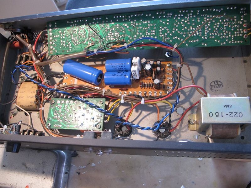
    1] new spague filter caps and electrolytics on the power supply board.
    2] twisted and lifted the heater wires
    3] tried various 12at7 phase inverter tubes. [a 12au7 did noticably quiet the amp, but lowered the volume too much]

    I found this info [scroll down to the Roland bolt 60 info] http://www.geocities.jp/dgb_studio/G_amp_e.htm
    and there's some info and a schematic about adding caps to the power supply to quiet the hum...but I dont really understand schematics enough to go for it. This is my gigging amp and I really need to keep it working! He talks here about adding them to the effects loop wires I think?

    Apparently all the info on mods for the Roland Bolt series amps was at one time available online here- Roland Bolt 60
    but this sight and its forum are defunct and the moderator is MIA :-(

    If any body has this info archived anywhere it would be invaluable to me!! I'd like to install a proper standby switch [the bolt's aren't true standby] and wire in a 3 spring reverb,all of which were at one time available on the Roland Bolt page....but its gone

    Again I'm not really confident with schematics so some hand holding would be needed

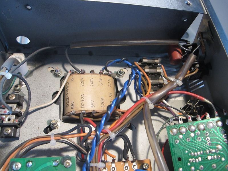
    Here's a gut shot of my bolt 30 after the cap job, just cause I like gut shots!


    Last edited by czech-one-2; 09-13-2014, 08:56 PM.
    https://soundcloud.com/damalistik/ro...ival-dubplatessigpic

  • #2
    service notes and schematics available here (click on "documents"): Roland Bolt 60

    The fact that the hum stops when you plug into "main in" means the problem is in the preamp. The power supply and power amp sections are ok and hum free.
    Originally posted by Enzo
    I have a sign in my shop that says, "Never think up reasons not to check something."


    Comment


    • #3
      If the hum is not coming from the reverb circuit a long shot..(the pot would have to be faulty too)
      check the pre supply it comes from the same winding as the bias for the o/p tubes.
      Should measure 47 volts at B. Couple of filter caps on the pre-board and D9 on the power supply board.
      D9 is a 500mw 47 volt zener.
      Q1 a 2SC1624 may be worth checking too.
      Attached Files

      Comment


      • #4
        Originally posted by oc disorder View Post
        If the hum is not coming from the reverb circuit a long shot..(the pot would have to be faulty too)
        check the pre supply it comes from the same winding as the bias for the o/p tubes.
        Should measure 47 volts at B. Couple of filter caps on the pre-board and D9 on the power supply board.
        D9 is a 500mw 47 volt zener.
        Q1 a 2SC1624 may be worth checking too.
        Thanks 4 the replies!
        I removed the reverb tank and wires as it sounded really weak anyway [belton brick reverb trumps it big time!]
        So I guess it looks like the preamp board is the source. I may just re-cap all the electrolytics on that long board with low ESR types and see if that helps.

        Just curious [and trying to learn], what made you single out D9, Q1, C21/C29 ?
        https://soundcloud.com/damalistik/ro...ival-dubplatessigpic

        Comment


        • #5
          Just curious [and trying to learn], what made you single out D9, Q1, C21/C29 ?
          Simply because that is the source of the pre-amp supply and as g-one suggests the hum must be in the preamp
          as you observed no hum when plugged into only the power amp in.
          At the top right of the schematic it shows B1 47 volts which comes from the B1 (mid lower left) from the power supply.
          That 47volt zener hold the supply at 47volts (sometimes + or - 2 volts).
          The two caps C21/C29 are the final filter caps for smoothing on the pre-amp supply rail.
          The power amp doesn't use this.
          I wouldn't necessarily replace all of those but as you were saying you were not confident with schematics, I was
          drawing your attention to those areas which , where hum is concerned are a good place to start and hopefully
          eliminate from the list. (C5 and C30 might be worth looking at too!)
          Being able to see the hum on an oscilloscope as ripple superimposed on the dc makes it easier to trace in some circumstances.
          Measuring the supply gives a few clues too .
          Sometimes I just "tack" lightly solder a similar known good cap over the supply at various points to see if I can hear a difference.
          Actually it's probably more likely it has a few cracked solder joints particularly an amp of it's age .
          Check around the switch and pots and any large loose objects !!
          Could even have a hairline crack on the pre-amp board or a loose ground somewhere.
          Last edited by oc disorder; 09-14-2014, 10:59 AM.

          Comment


          • #6
            Q1 is the main element of a circuit called a 'Series Pass Regulator'.
            Transistor-Zener Diode Regulator Circuits
            Series Voltage Regulator | Series Pass Regulator | Tutorial

            C21 & C29 capacitors help smooth out any ripple riding on the output voltage.

            Check the dc voltage at TP 15V & TP 7.5V.
            It should be a steady dc reading.
            Then flip your meter to read Volts AC & read the same two points again.
            There should be a very low ac reading (ideally zero).
            Last edited by Jazz P Bass; 09-14-2014, 11:30 AM.

            Comment


            • #7
              Originally posted by Jazz P Bass View Post
              Q1 is the main element of a circuit called a 'Series Pass Regulator'.
              Transistor-Zener Diode Regulator Circuits
              Series Voltage Regulator | Series Pass Regulator | Tutorial

              C21 & C29 capacitors help smooth out any ripple riding on the output voltage.

              Check the dc voltage at TP 15V & TP 7.5V.
              It should be a steady dc reading.
              Then flip your meter to read Volts AC & read the same two points again.
              There should be a very low ac reading (ideally zero).
              Thanks, I'll check TP 15V and TP 7.5v ...if you can tell me which component/location that is.
              I'll read the 'SVR' tutorial today, thanks!
              Also, is there a common sub for the 2sc1624 ? I have some L7812CV voltage regulators here..
              Also, would a 1N5368 zener be suitable for D9? http://www.gme.cz/1n5368b-p222-195

              And one more question, the two blue 16uf filter caps were originally 22uf, but I upped the large single filter cap from 47uf to 80uf. Any problem there?
              Last edited by czech-one-2; 09-14-2014, 02:15 PM.
              https://soundcloud.com/damalistik/ro...ival-dubplatessigpic

              Comment


              • #8
                Originally posted by oc disorder View Post
                Actually it's probably more likely it has a few cracked solder joints particularly an amp of it's age .
                Check around the switch and pots and any large loose objects !!
                Could even have a hairline crack on the pre-amp board or a loose ground somewhere.
                Ok, I inspected and re-flowed the pots, all terminals and a few suspicious areas. Still buzzing. The 'main in' is utterly silent from buzz. The buzz has nothing to do with volume/gain/eq tweeks.The buzz is the same with the volume at zero or 10.
                I tried the 'chopstick' method on all the wires to see if any movment changed the buzz, nope...
                Last edited by czech-one-2; 09-14-2014, 02:16 PM.
                https://soundcloud.com/damalistik/ro...ival-dubplatessigpic

                Comment


                • #9
                  Originally posted by oc disorder View Post
                  The two caps C21/C29 are the final filter caps for smoothing on the pre-amp supply rail.
                  The power amp doesn't use this.
                  I wouldn't necessarily replace all of those but as you were saying you were not confident with schematics, I was
                  drawing your attention to those areas which , where hum is concerned are a good place to start and hopefully
                  eliminate from the list. (C5 and C30 might be worth looking at too!)
                  Would it be wise to up the capacitance of C21 /C29 from 100/220uf to,say, 220/330uf ?
                  https://soundcloud.com/damalistik/ro...ival-dubplatessigpic

                  Comment


                  • #10
                    Why?

                    Comment


                    • #11
                      It may help to try running a cord from the Pre Out jack to the Main In jack.

                      There are Normally Closed contacts on the jacks that get crudy.
                      The jumper cord will remove those contacts from the equation.

                      Comment


                      • #12
                        Better filtering?
                        https://soundcloud.com/damalistik/ro...ival-dubplatessigpic

                        Comment


                        • #13
                          no difference
                          https://soundcloud.com/damalistik/ro...ival-dubplatessigpic

                          Comment


                          • #14
                            Unless you actually measure the TP for steady Vdc & how much Vac is riding on them, it is rather poinless to consider upping the values, is it not?

                            You could simply throw parts at it.
                            It may very well fix it.
                            But you will not know what the root cause was.

                            Comment


                            • #15
                              Originally posted by Jazz P Bass View Post
                              Unless you actually measure the TP for steady Vdc & how much Vac is riding on them, it is rather poinless to consider upping the values, is it not?

                              You could simply throw parts at it.
                              It may very well fix it.
                              But you will not know what the root cause was.
                              Right, now where do I measure the TP? Sorry, but I need some guidance on this
                              https://soundcloud.com/damalistik/ro...ival-dubplatessigpic

                              Comment

                              Working...
                              X